
Datasheet


V
OVL
= [(R1 + R2) x (1.16V) - 23 PA)] + 1.16V
R3
V
OVH
=
1.16V x (R1 + R2 + R3)
R3
V
UVL
=
1.16V x (R1 + R2 + R3)
R2 + R3
V
UVH
= 1.16V + [R1 x (23 PA +
(R2 + R3)
1.16V
)]
R2 =
1.16V x R1
(7V ± 1.16V)
- R3 = 4.61 k:
R3 =
1.16V x R1 x 7V
15V x (7V - 1.16V)
= 4.03 k:
R1 =
8V - 7V
23 PA
=
1V
= 43.5 k:
23 PA
V
OVL
= [(R1 + R2) x ((1.16V) - 23 PA)] + 1.16V
R3
R2 =
1.16V x R1
V
UVL
- 1.16V
- R3
R3 =
1.16V x R1 x V
UVL
V
OVH
x (V
UVL
± 1.16V)
R1 =
V
UVH
- V
UVL
23 PA
=
V
UV(HYS)
23 PA
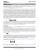
VIN
UVLO/EN
OVLO
GND
R1
R2
R3
1.16V
1.16V
23 PA
TIMER AND
GATE
LOGIC CONTROL
LM25066I/A
V
SYS
23 PA
LM25066I, LM25066IA
SNVS824C –JUNE 2012–REVISED MARCH 2013
www.ti.com
Figure 41. UVLO and OVLO Thresholds Set By R1-R3
The procedure to calculate the resistor values is as follows:
• Choose the upper UVLO threshold (V
UVH
), and the lower UVLO threshold (V
UVL
).
• Choose the upper OVLO threshold (V
OVH
).
• The lower OVLO threshold (V
OVL
) cannot be chosen in advance in this case, but is determined after the
values for R1-R3 are determined. If V
OVL
must be accurately defined in addition to the other three thresholds,
see Option B below. The resistors are calculated as follows:
(11)
(12)
(13)
The lower OVLO threshold is calculated from:
(14)
As an example, assume the application requires the following thresholds: V
UVH
= 8V, V
UVL
= 7V, V
OVH
= 15V.
(15)
(16)
(17)
The lower OVLO threshold calculates to 12.03V and the OVLO hysteresis is 2.97V. Note that the OVLO
hysteresis is always slightly greater than the UVLO hysteresis in this configuration. When the R1-R3 resistor
values are known, the threshold voltages and hysteresis are calculated from the following:
(18)
(19)
V
UV(HYS)
= R1 x 23µA (20)
(21)
(22)
V
OV(HYS)
= (R1 + R2) x 23µA (23)
26 Submit Documentation Feedback Copyright © 2012–2013, Texas Instruments Incorporated
Product Folder Links: LM25066I LM25066IA