
Datasheet


0.0 0.2 0.4 0.6 0.8 1.0 1.2
5
10
15
20
25
30
35
40
45
INPUT VOLTAGE (v)
SHORT CIRCUIT VOLTAGE (v)
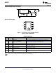
SAFE OPERATING AREA
0.0 0.2 0.4 0.6 0.8 1.0 1.2
5
10
15
20
25
30
35
40
45
INPUT VOLTAGE (v)
SHORT CIRCUIT VOLTAGE (v)
SAFE OPERATING AREA
0.0 0.2 0.4 0.6 0.8 1.0 1.2
5
10
15
20
25
30
35
40
45
INPUT VOLTAGE (v)
SHORT CIRCUIT VOLTAGE (v)
SAFE OPERATING AREA
LM22671
SNVS589M –SEPTEMBER 2008–REVISED APRIL 2013
www.ti.com
Figure 15. SOA at 300 kHz Figure 16. SOA at 500 kHz
Figure 17. SOA at 800 kHz
Soft-Start
The soft-start feature allows the regulator to gradually reach steady-state operation, thus reducing start-up
stresses. The internal soft-start feature brings the output voltage up in about 500 µs. This time can be extended
by using an external capacitor connected to the SS pin. Values in the range of 100 nF to 1 µF are recommended.
The approximate soft-start time can be estimated from the following equation:
(8)
Soft-start is reset any time the part is shut down or a thermal overload event occurs.
Switching Frequency Adjustment and Synchronization
The LM22671 will operate in three different modes, depending on the condition of the RT/SYNC pin. With the
RT/SYNC pin floating, the regulator will switch at the internally set frequency of 500 kHz (typ.). With a resistor in
the range of 25 kΩ to 200 kΩ, connected from RT/SYNC to ground, the internal switching frequency can be
adjusted from 1MHz to 200 kHz. Figure 18 shows the typical curve for switching frequency vs. the external
resistance connected to the RT/SYNC pin. The accuracy of the switching frequency, in this mode, is slightly
worse than that of the internal oscillator; about +/- 25% is to be expected. Finally, an external clock can be
applied to the RT/SYNC pin to allow the regulator to synchronize to a system clock or another LM22671. The
mode is set during start-up of the regulator. When the LM22671 is enabled, or after V
IN
is applied, a weak pull-up
is connected to the RT/SYNC pin and, after approximately 100 µs, the voltage on the pin is checked against a
threshold of about 0.8V. With the RT/SYNC pin open, the voltage floats above this threshold, and the mode is set
to run with the internal clock. With a frequency set resistor present, an internal reference holds the pin voltage at
0.8V; the resulting current sets the mode to allow the resistor to control the clock frequency. If the external circuit
forces the RT/SYNC pin to a voltage much greater or less than 0.8v, the mode is set to allow external
synchronization. The mode is latched until either the EN or the input supply is cycled.
10 Submit Documentation Feedback Copyright © 2008–2013, Texas Instruments Incorporated
Product Folder Links: LM22671