
Datasheet


MECHANICAL DATA
MCDI039 – AUGUST 2001
1
POST OFFICE BOX 655303 • DALLAS, TEXAS 75265
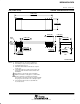
JVD (R-CDIP-T16/40) CERAMIC SIDE-BRAZE DUAL-IN-LINE
4202636/A 08/01
Seating
Plane
Plane
Base
Area
Index
2.030 (51,56)
1.980 (50,29)
1 20
2140
0.580 (14,73)
0.610 (15,49)
0.060 (1,52)
0.038 (0,97)
0.100 (2,54) TYP
0.015 (0,38)
0.023 (0,58)
0.030 (0,76)
0.065 (1,65)
0.125 (3,18)
0.175 (4,45)
0.085 (2,16)
0.190 (4,83)
0.020 (0,51)
0.070 (1,78)
0.595 (15,11)
0.625 (15,88)
TYP
0.600 (15,24)
0.012 (0,30)
0.008 (0,20)
0°–15°
G
G
G
F
NOTES: A. All linear dimensions are in inches (millimeters).
B. This drawing is subject to change without notice.
C. Controlling dimension: inch.
D. Falls within JEDEC MO–038–AC with the exception
of lead count.
E. Leads within 0.005 (0,13) radius of true position (TP)
at gage plane with maximum material condition and
unit installed.
F. Angle applies to spread leads prior to installation.
G. Outlines on which the seating plane is coincident with
the plane (standoff = 0), terminals lead standoffs
are not required, and lead shoulder may equal lead width
along any part of the lead above the seating/base plane.
H. A visual index feature must be located within the
cross-hatched area.