
Datasheet


11
®
INA121
INA121
Transducer
C
1
C
2
Null
R
2
R
1
R
G
V
O
Ref
V
AC
INA121
OPA277
C
1
50nF
R
G
R
2
R
G
Make G ≤ 10 where G = 1 +
50k
Load
V
IN
G
•
R
2
I
L
=
R
1
10kΩ
V
IN
Ref
INA121
R
G
V
O
C
1
0.1µF
OPA277
Ref
R
1
1MΩ
f
–3dB
=
1
2πR
1
C
1
= 1.59Hz
V
IN
+
–
INA121 ISO124
±6V to ±18V
Isolated Power
±15V
Ref
V
IN
–
V
IN
+
V
O
Isolated
Common
V+ V–
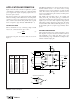
FIGURE 8. Galvanically Isolated Instrumentation
Amplifier.
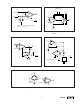
FIGURE 7. High-Pass Input Filter.
FIGURE 10. Voltage Controlled Current Source.FIGURE 9. AC-Coupled Instrumentation Amplifier.
INA121
C
1
C
2
R
1
R
2
V
O
2πR
1
C
1
1
f
c
=
NOTE: To preserve good low frequency CMR,
make R
1
= R
2
and C
1
= C
2
.
R
G
Ref
FIGURE 11. Capacitive Bridge Transducer Circuit.