
Datasheet


DS26C32AM, DS26C32AT
www.ti.com
SNLS382C –JUNE 1998–REVISED APRIL 2013
TEST AND SWITCHING WAVEFORMS
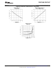
Figure 3. Propagation Delay
C
L
includes load and test jig capacitance.
S
1
= V
CC
for t
PZL
, and t
PLZ
measurements.
S
1
= Gnd for t
PZH
and t
PHZ
measurements.
Figure 4. Test Circuit for TRI-STATE Output Tests
Figure 5. TRI-STATE Output Enable and Disable Waveforms
AC Test Circuit and Switching Time Waveforms
Figure 6. Load Test Circuit for TRI-STATE Outputs for “LS-Type” Load
Copyright © 1998–2013, Texas Instruments Incorporated Submit Documentation Feedback 5
Product Folder Links: DS26C32AM DS26C32AT