
Datasheet


Acceleration (g)
¦
(RESONANCE)
Frequency (Hz)
+
±
V
O
Motor-spin
direction
I
L
I
L
OUT+
OUT±
±
+
V
O
Motor-spin
direction
I
L
I
L
OUT+
OUT±
DRV2605
www.ti.com
SLOS825C –DECEMBER 2012–REVISED SEPTEMBER 2014
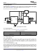
Figure 57. Motor Spin Direction in ERM Motors
Another common approach to driving DC motors is the concept of overdrive voltage. To overcome the inertia of
the mass of the motor, these motors are often overdriven for a short amount of time before returning to the rated
voltage of the motor to sustain the rotation of the motor. Overdrive is also used to stop (or brake) a motor quickly.
Refer the data sheet of the motor for safe and reliable overdrive voltage and duration.
8.2.2.1.2 Linear Resonance Actuators (LRA)
Linear resonant actuators (LRAs) vibrate optimally at the resonant frequency. LRAs have a high-Q frequency
response because of a rapid drop in vibration performance at the offsets of 3 to 5 Hz from the resonant
frequency. Many factors also cause a shift or drift in the resonant frequency of the actuator such as temperature,
aging, the mass of the product to which the LRA is mounted, and in the case of a portable product, the manner in
which the product is held. Furthermore, as the actuator is driven to the maximum allowed voltage, many LRAs
will shift several hertz in frequency because of mechanical compression. All of these factors make a real-time
tracking auto-resonant algorithm critical when driving LRA to achieve consistent, optimized performance.
Figure 58. Typical LRA Response
8.2.2.1.2.1 Auto-Resonance Engine for LRA
The DRV2605 auto-resonance engine tracks the resonant frequency of an LRA in real time effectively locking
into the resonance frequency after half a cycle. If the resonant frequency shifts in the middle of a waveform for
any reason, the engine tracks the frequency from cycle to cycle. The auto resonance engine accomplishes this
tracking by constantly monitoring the back-EMF of the actuator. Note that the auto resonance engine is not
affected by the auto-calibration process which is only used for level calibration. No calibration is required for the
auto resonance engine.
8.2.2.2 Capacitor Selection
The DRV2605 device has a switching output stage which pulls transient currents through the V
DD
pin. Placing a
0.1-µF low equivalent-series-resistance (ESR) supply-bypass capacitor of the X5R or X7R type near the V
DD
supply pin is recommended for proper operation of the output driver and the digital portion of the device. Place a
1-µF X5R or X7R-type capacitor from the REG pin to ground.
Copyright © 2012–2014, Texas Instruments Incorporated Submit Documentation Feedback 49
Product Folder Links: DRV2605