
Datasheet


Input
Steady-State
Output Magnitude
OD_CLAMP[7:0]
0 V
Open Loop
ERM_OPEN_LOOP = 1 OR LRA_OPEN_LOOP = 1
PWM
Input Interface
0% 50% 100%
RTP (8-bit) DATA_FORMAT_RTP = 1
0x00 0x7F 0xFF
0x81 0x00 0x7F
-OD_CLAMP[7:0]
RTP (8-bit) DATA_FORMAT_RTP = 0
DRV2605
SLOS825C –DECEMBER 2012 –REVISED SEPTEMBER 2014
www.ti.com
Programming (continued)
7.5.8 Waveform Playback Programming
7.5.8.1 Data Formats for Waveform Playback
The DRV2605 smart-loop architecture has three modes of operation. Each of these modes can drive either ERM
or LRA devices.
1. Open-loop mode
2. Closed-loop mode (unidirectional)
3. Closed-loop mode (bidirectional)
Each mode has different advantages and disadvantages. The DRV2605 device brings new cutting-edge actuator
control with closed-loop operation around the back-EMF for automatic overdrive and braking. However, some
existing haptic implementations already include overdrive and braking that are embedded in the waveform data.
Open-loop mode is used to preserve compatibility with such systems.
The following sections show how the input data for each DRV2605 interface is translated to the output drive
signal.
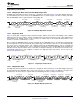
7.5.8.1.1 Open-Loop Mode
In open-loop mode, the reference level for full-scale drive is set by the OD_CLAMP[7:0] bit in Register 0x17. A
mid-scale input value gives no drive signal, and a less-than mid-scale gives a negative drive value. For an ERM,
a negative drive value results in counter-rotation, or braking. For an LRA, a negative drive value results in a 180-
degree phase shift in commutation.
The RTP mode has 8 bits of resolution over the I
2
C bus. The RTP data can either be in a signed (2s
complement) or unsigned format as defined by the DATA_FORMAT_RTP bit.
Figure 24.
26 Submit Documentation Feedback Copyright © 2012–2014, Texas Instruments Incorporated
Product Folder Links: DRV2605