
Datasheet


DRV101
9
SBVS008B
www.ti.com
APPLICATIONS INFORMATION
POWER SUPPLY
The DRV101 operates from a single +9V to +60V supply
with excellent performance. Most behavior remains un-
changed throughout the full operating voltage range. Param-
eters which vary significantly with operating voltage are
shown in the Typical Performance Curves.
ADJUSTABLE INITIAL 100% DUTY CYCLE
A unique feature of the DRV101 is its ability to provide an
initial constant dc output (100% duty cycle) and then switch
to PWM mode to save power. This function is particularly
useful when driving solenoids which have a much higher
pull-in current requirement than hold requirement.
The duration of this constant dc output (before PWM output
begins) can be externally controlled with a capacitor con-
nected from Delay Adjust (pin 2) to ground according to the
following equation:
Delay Time ≈ C
D
• 10
6
(time in seconds, C
D
in Farads)
Leaving the Delay Adjust pin open results in a constant
output time of approximately 15µs. The duration of this
initial output can be reduced to less than 3µs by connecting
the pin to 5V. Table I provides examples of desired “delay”
times (constant output before PWM mode) and the appropri-
ate capacitor values or pin connection.
CONSTANT OUTPUT DURATION C
D
3µs Pin connected to 5V
15µs Pin open
100µs 100pF
1ms 1nF
100ms 0.1µF
TABLE I. Delay Adjust Pin Connections.
ADJUSTABLE DUTY CYCLE
The DRV101’s externally adjustable duty cycle provides an
accurate means of controlling power delivered to the load.
Duty cycle can be set from 10% to 100% with an external
resistor, analog voltage, or the output of a D/A converter.
Reduced duty cycle results in reduced power dissipation.
This keeps the DRV101 and load cooler, resulting in in-
creased reliability for both devices. PWM frequency is a
constant 24kHz.
Resistor Controlled Duty Cycle
Duty cycle is easily programmed with a resistor (R
PWM
)
connected between the Duty Cycle Adjust pin and ground.
Increased resistor values correspond to decreased duty cycles.
Table II provides resistor values for typical duty cycles.
Resistor values for additional duty cycles can be obtained
from Figure 3. For reference purposes, the equation for
calculating R
PWM
is included in Figure 3.
FIGURE 3. R
PWM
vs Duty Cycle.
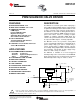
FIGURE 2. Simplified Circuit Model of the Delay Adjust Pin.
The internal Delay Adjust circuitry is composed of a 3µA
current source and a 3V comparator as shown in Figure 2.
Thus, when the pin voltage is less than 3V, the output device
is 100% on (dc output mode).
3µA
2
C
D
V
S
3V Reference
Comparator
Delay Adjust
DRV101
RESISTOR
(1)
VOLTAGE
(2)
DUTY CYCLE R
PWM
(kΩ)V
PWM
(V)
10 976 3.7
20 205 3.4
30 84.5 3.0
40 46.4 2.6
50 28.7 2.2
60 18.2 1.75
70 11.8 1.35
80 7.50 1.00
90 4.87 0.75
NOTES: (1) Resistor values listed are nearest 1% standard values. (2) Do not
drive pin below 0.1V. For additional values, see “Duty Cycle vs Voltage” typical
performance curve.
TABLE II. Duty Cycle Adjust. T
A
= +25°C, V
S
= +24V.
10 20 40 60 10080
Duty Cycle (%)
R
PWM
(kΩ)
1000
100
10
1
R
PWM
= [ a + b (DC) + c (DC)
2
+ d (DC)
3
+ e (DC)
4
]
–1
where: a = 2.4711 x 10
–6
b = –5.2095 x 10
–7
c = 4.4576 x 10
–8
d = –7.6427 x 10
–10
e = 6.8039 x 10
–12
R
PWM
= [2.4711 x 10
–6
+ (–5.2095 x 10
–7)
(50) + (4.4576 x 10
–8
) (50)
2
+ (–7.6427 x 10
–10
) (50)
3
+ (6.8039 x 10
–12
) (50)
4
]
–1
DC = duty cycle in %
For 50% duty cycle:
= 28.7kΩ