
Datasheet


www.national.com 18
DP83848J
2.4 LED INTERFACE
The DP83848J supports configurable Light Emitting Diode
(LED) pins for configuring the link and speed. The PHY
Control Register (PHYCR) for the LED can also be
selected through address 19h, bit [5].
See Table 3. for LED Mode selection of DP83848J.
The LED_LINK pin in Mode 1 indicates the link status of
the port. In 100BASE-T mode, link is established as a
result of input receive amplitude compliant with the TP-
PMD specifications which will result in internal generation
of signal detect. A 10 Mb/s Link is established as a result
of the reception of at least seven consecutive normal Link
Pulses or the reception of a valid 10BASE-T packet. This
will cause the assertion of LED_LINK. LED_LINK will
deassert in accordance with the Link Loss Timer as speci-
fied in the IEEE 802.3 specification.
The LED_LINK pin in Mode 1 will be OFF when no LINK is
present.
The LED_LINK pin in Mode 2 will be ON to indicate Link is
good and BLINK to indicate activity is present on either
transmit or receive activity.
The LED_SPEED pin in DP83848J indicates 10 or 100
Mb/s data rate of the port. The standard CMOS driver
goes high when operating in 100Mb/s operation. The
functionality of this LED is independent of the mode
selected.
Since these LED pins are also used as strap options, the
polarity of the LED is dependent on whether the pin is
pulled up or down.
2.4.1 LED
Since the Auto-Negotiation strap options share the LED
output pins, the external components required for strap-
ping and LED usage must be considered in order to avoid
contention.
Specifically, when the LED output is used to drive the LED
directly, the active state of the output driver is dependent
on the logic level sampled by the AN input upon power-
up/reset. For example, if the AN input is resistively pulled
low then the corresponding output will be configured as an
active high driver. Conversely, if the AN input is resistively
pulled high, then the corresponding output will be config-
ured as an active low driver.
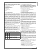
Refer to Figure 3 for an example of AN connection to ex-
ternal components. In this example, the AN strapping re-
sults in Auto-Negotiation with 10BASE-T Half-Duplex ,
100BASE-TX, Half-Duplex advertised.
The adaptive nature of the LED output helps to simplify
potential implementation issues of this dual purpose pin.
.
2.4.2 LED Direct Control
The DP83848J provides another option to directly control
the LED outputs through the LED Direct Control Register
(LEDCR), address 18h. The register does not provide
read access to the LED.
Table 3. LED Mode Select for DP83848J
Mode
LED_CFG[0]
(bit 5) or (pin 33)
LED_LINK LED_SPEED
1 1 ON for Good
Link
OFF for No
Link
ON in 100Mb/s
OFF in 10Mb/s
2 0 ON for Good
Link
BLINK for
Activity
ON in 100Mb/s
OFF in 10Mb/s
LED_LINK
VCC
275Ω
AN0 = 0
2.2kΩ
LED_SPEED
AN1 = 1
275Ω
Figure 3. AN Strapping and LED Loading Example