
Datasheet


www.national.com 34
DP83848I
5.2 ESD Protection
Typically, ESD precautions are predominantly in effect
when handling the devices or board before being installed
in a system. In those cases, strict handling procedures
need be implemented during the manufacturing process to
greatly reduce the occurrences of catastrophic ESD
events. After the system is assembled, internal compo
-
nents are less sensitive from ESD events.
See Section 8.0 for ESD rating.
5.3 Clock In (X1) Requirements
The DP83848I supports an external CMOS level oscillator
source or a crystal resonator device.
Oscillator
If an external clock source is used, X1 should be tied to the
clock source and X2 should be left floating.
Specifications for CMOS oscillators: 25 MHz in MII Mode
and 50 MHz in RMII Mode are listed in
Table 7 and Table 8.
Crystal
A 25 MHz, parallel, 20 pF load crystal resonator should be
used if a crystal source is desired. Figure 12 shows a typi-
cal connection for a crystal resonator circuit. The load
capacitor values will vary with the crystal vendors; check
with the vendor for the recommended loads.
The oscillator circuit is designed to drive a parallel reso-
nance AT cut crystal with a minimum drive level of 100µW
and a maximum of 500
µW. If a crystal is specified for a
lower drive level, a current limiting resistor should be
placed in series between X2 and the crystal.
As a starting point for evaluating an oscillator circuit, if the
requirements for the crystal are not known, C
L1
and C
L2
should be set at 33 pF, and R
1
should be set at 0Ω.
Specification for 25 MHz crystal are listed in Ta ble 9.
Figure 12. Crystal Oscillator Circuit
X1
X2
C
L2
C
L1
R
1
Table 6.
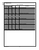
Table 7. 25 MHz Oscillator Specification
Parameter Min Typ Max Units Condition
Frequency 25 MHz
Frequency
Tolerance
+50 ppm Operational Temperature
Frequency
Stability
+50 ppm 1 year aging
Rise / Fall Time 6 nsec 20% - 80%
Jitter
800
1
psec Short term
Jitter
800
1
psec Long term
Symmetry 40% 60% Duty Cycle
1
This limit is provided as a guideline for component selection and to guaranteed by production testing.
Refer to AN-1548, “PHYTER 100 Base-TX Reference Clock Jitter Tolerance,“ for details on jitter performance.