
Datasheet


www.ti.com
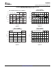
POWER-DOWN MODES
V X
OUT
Amplifier
Resistor
String
DAC
Power-Down
Circuitry
Resistor
Network
DAC8554
SLAS431B – JUNE 2005 – REVISED OCTOBER 2006
Individual channels can be separately powered
down, reducing the total power consumption. When
The DAC8554 utilizes four modes of operation.
all channels are powered down, the DAC8554 power
These modes are accessed by setting three bits
consumption drops below 2 µ A. There is no power-up
(PD2, PD1, and PD0) in the shift register and
command. When a channel is updated with data, it
performing a Load action to the DACs. The
automatically exits power-down. All channels exit
DAC8554 offers a very flexible power-down interface
power-down simultaneously after a broadcast data
based on channel register operation. A channel
update. The time to exit power-down is
consists of a single 16-bit DAC with power-down
approximately 5 µ s. See Table 1 and Table 2 for
circuitry, a temporary storage register (TR), and a
power-down operation details.
DAC register (DR). TR and DR are both 18 bits wide.
Two MSBs represent a power-down condition and 16
LSBs represent data for TR and DR. By adding bits
17 and 18 to TR and DR, a power-down condition
can be temporarily stored and used as data. Internal
circuits ensure that DB15 and DB14 get transferred
to TR17 and TR16 (DR17 and DR16), when DB16 =
1.
The DAC8554 treats the power-down condition as
data; all the operational modes are still valid for
power-down. It is possible to broadcast a
power-down condition to all the DAC8554s in a
Figure 49. Output Stage During Power-Down
system, or it is possible to simultaneously
(High-Impedance)
power-down a channel while updating data on other
channels.
DB16, DB15, and DB14 = '100' (or '111') represent a
power-down condition with Hi-Z output impedance
for a selected channel. '101' represents a
power-down condition with 1k Ω output impedance,
and '110' represents a power-down condition with
100k Ω output impedance.
18
Submit Documentation Feedback