
Datasheet


9
®
DAC7614
THEORY OF OPERATION
The DAC7614 is a quad, serial input, 12-bit, voltage output
DAC. The architecture is a classic R-2R ladder configuration
followed by an operational amplifier that serves as a buffer.
Each DAC has its own R-2R ladder network and output op
amp, but all share the reference voltage inputs. The minimum
voltage output (“zero-scale”) and maximum voltage output
(“full-scale”) are set by external voltage references (V
REFL
and V
REFH
, respectively). The digital input is a 16-bit serial
word that contains the 12-bit DAC code and a 2-bit address
code that selects one of the four DACs (the two remaining
bits are unused). The converter can be powered from a single
+5V supply or a dual ±5V supply. Each device offers a reset
function which immediately sets all DAC output voltages and
internal registers to either zero-scale (code 000
H
) or mid-scale
(code 800
H
). The reset code is selected by the state of the
RESETSEL pin (LOW = 000
H
, HIGH = 800
H
). See Figures
1 and 2 for the basic operation of the DAC7614.
ANALOG OUTPUTS
When V
SS
= –5V (dual supply operation), the output
amplifier can swing to within 2.25V of the supply rails,
over the –40°C to +85°C temperature range. With V
SS
= 0V
(single-supply operation), the output can swing to ground.
Note that the settling time of the output op amp will be
longer with voltages very near ground. Also, care must be
taken when measuring the zero-scale error when V
SS
= 0V.
If the output amplifier has a negative offset, the output
voltage may not change for the first few digital input codes
(000
H
, 001
H
, 002
H
, etc.) since the output voltage cannot
swing below ground.
The behavior of the output amplifier can be critical in some
applications. Under short-circuit conditions (DAC output
shorted to ground), the output amplifier can sink a great deal
more current than it can source. See the Specifications table
for more details concerning short-circuit current.
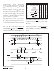
FIGURE 1. Basic Single-Supply Operation of the DAC7614.
FIGURE 2. Basic Dual-Supply Operation of the DAC7614.
NOTES: (1) P and U package pin configurations shown. (2) As configured, RESET LOW sets all internal registers
to code 000
H
(0V). If RESETSEL is HIGH, RESET LOW sets all internal registers to code 800
H
(1.25V).
1
2
3
4
5
6
7
8
16
15
14
13
12
11
10
9
V
DD
V
OUTD
V
OUTC
V
REFL
V
REFH
V
OUTB
V
OUTA
V
SS
RESETSEL
RESET
LOADDACS
NIC
CS
CLK
SDI
GND
Reset DACs
(2)
Update Selected Register
Chip Select
Clock
Serial Data In
DAC7614
(1)
0.1µF
0.1µF
0V to +2.5V
1µF to 10µF
+5V
+
0V to +2.5V
0V to +2.5V
0V to +2.5V
+2.500V
NOTES: (1) P and U package pin configurations shown. (2) As configured, RESET LOW sets all internal register
to code 800
H
(0V). If RESETSEL is LOW, RESET LOW sets all internal registers to code 000
H
(–2.5V).
1
2
3
4
5
6
7
8
16
15
14
13
12
11
10
9
V
DD
V
OUTD
V
OUTC
V
REFL
V
REFH
V
OUTB
V
OUTA
V
SS
RESETSEL
RESET
LOADDACS
NIC
CS
CLK
SDI
GND
Reset DACs
(2)
Update Selected Register
Chip Select
Clock
Serial Data In
DAC7614
(1)
0.1µF
0.1µF
–2.5V to +2.5V
1µF to 10µF
+5V
–5V
+
0.1µF
1µF to 10µF
+
–2.5V to +2.5V
–2.500V
0.1µF
+2.500V
–2.5V to +2.5V
–2.5V to +2.5V
+5V