
Datasheet


Non-Harmonic Clock-Related Spurious Signals
DAC5686
www.ti.com
............................................................................................................................................................ SLWS147F – APRIL 2003 – REVISED JUNE 2009
Table 3. Clock-Mode Configuration (continued)
CLOCK MODE PLLVDD DIV[1:0] SEL[1:0] DATA RATE (MSPS) PLLLOCK PIN FUNCTION
Non-interleaved input data; internal PLL on; DA[15:0] data rate matches DB[15:0] data rate.
Internal 2 × 3.3 V 00 00 125 to 160 Internal PLL lock indicator
Internal 2 × 3.3 V 01 00 62.5 to 125 Internal PLL lock indicator
Internal 2 × 3.3 V 10 00 31.25 to 62.5 Internal PLL lock indicator
Internal 2 × 3.3 V 11 00 15.63 to 31.25 Internal PLL lock indicator
Internal 4 × 3.3 V 00 01 62.5 to 125 Internal PLL lock indicator
Internal 4 × 3.3 V 01 01 31.25 to 62.5 Internal PLL lock indicator
Internal 4 × 3.3 V 10 01 15.63 to 31.25 Internal PLL lock indicator
Internal 4 × 3.3 V 11 01 7.8125 to 15.625 Internal PLL lock indicator
Internal 8 × 3.3 V 00 10 31.25 to 62.5 Internal PLL lock indicator
Internal 8 × 3.3 V 01 10 15.63 to 31.25 Internal PLL lock indicator
Internal 8 × 3.3 V 10 10 7.8125 to 15.625 Internal PLL lock indicator
Internal 8 × 3.3 V 11 10 3.9 to 7.8125 Internal PLL lock indicator
Internal 16 × 3.3 V 00 11 15.625 to 31.25 Internal PLL lock indicator
Internal 16 × 3.3 V 01 11 7.8125 to 15.625 Internal PLL lock indicator
Internal 16 × 3.3 V 10 11 3.9062 to 7.8125 Internal PLL lock indicator
Interleaved input data on the DA[15:0] input pins; internal PLL on
Internal 2 × 3.3 V 00 00 Not recommended Internal PLL lock indicator
Internal 2 × 3.3 V 01 00 62.5 to 80 Internal PLL lock indicator
Internal 2 × 3.3 V 10 00 31.25 to 62.5 Internal PLL lock indicator
Internal 2 × 3.3 V 11 00 15.625 to 31.25 Internal PLL lock indicator
Internal 4 × 3.3 V 00 01 62.5 to 80 Internal PLL lock indicator
Internal 4 × 3.3 V 01 01 31.25 to 62.5 Internal PLL lock indicator
Internal 4 × 3.3 V 10 01 15.625 to 31.25 Internal PLL lock indicator
Internal 4 × 3.3 V 11 01 7.8125 to 15.625 Internal PLL lock indicator
Internal 8 × 3.3 V 00 10 31.25 to 62.5 Internal PLL lock indicator
Internal 8 × 3.3 V 01 10 15.625 to 31.25 Internal PLL lock indicator
Internal 8 × 3.3 V 10 10 7.8125 to 15.625 Internal PLL lock indicator
Internal 8 × 3.3 V 11 10 3.9062 to 7.8125 Internal PLL lock indicator
Internal 16 × 3.3 V 00 11 15.625 to 31.25 Internal PLL lock indicator
Internal 16 × 3.3 V 01 11 7.8125 to 15.625 Internal PLL lock indicator
Internal 16 × 3.3 V 10 11 3.9062 to 7.8125 Internal PLL lock indicator
Internal 16 × 3.3 V 11 11 1.9531 to 3.9062 Internal PLL lock indicator
In interpolating DACs, imperfect isolation between the digital and DAC clock circuits generates spurious signals
at frequencies related to the DAC clock rate. The digital interpolation filters in these DACs run at sub-harmonic
frequencies of the output rate clock, where these frequencies are f
DAC
/2
N
, N = 1 – 4. For example, for 2 ×
interpolation there is only one interpolation filter running at f
DAC
/2; for 4 × interpolation, on the other hand, there
are two interpolation filters running at f
DAC
/2 and f
DAC
/4. These lower-speed clocks for the interpolation filter mix
with the DAC clock circuit and create spurious images of the wanted signal and second Nyquist-zone image at
offsets of f
DAC
/2
N
.
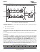
The location of these spurious signals is determined by whether the DAC5686 output is used as a complex
signal to be feed to an analog quadrature modulator or as a real IF signal. Figure 28 (a) shows the location of the
largest spurious signals for f
DAC
= 500 MSPS and 4 × interpolation for a complex output signal. At the output of
the analog quadrature modulator, the spurious signals with negative frequencies appear on the opposite
sideband from the wanted signal. The closest spurious signal results from the wanted signal mixing with the
f
DAC
/4 interpolation-filter clock, which in this example is 125 MHz from the wanted signal for all IF frequencies.
Copyright © 2003 – 2009, Texas Instruments Incorporated Submit Documentation Feedback 27
Product Folder Link(s): DAC5686