
Datasheet


Testing and Configuration
www.ti.com
2.5 DAC31x2EVM Configuration for DAC Output
Follow this procedure to configure the DAC31x2EVM in order to test the EVM signal output.
Step 1. Four 0-Ω resistors must be moved in order to configure the output of the DAC31x2 as 1:1
transformer-coupled.
• Remove the resistors R109, R110, R111, and R112
• Install the resistors R211, R207, R191, and R195
Step 2. Provide the clock input: 491.52 MHz at 1.5 V
RMS
at the J9 SMA connector of the
DAC31x2EVM.
Step 3. Turn on power to the board at J12/J13.
Step 4. Verify the spectrum using the Spectrum Analyzer at the two DAC outputs of the
DAC31x2EVM (J3 and J2).
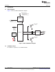
Figure 5 illustrates a typical transformer-coupled output using a wave analyzer.
Figure 5. DAC3162EVM Transformer-Coupled Output at 30 MHz IF
6
DAC31x2EVM SBOU096A–November 2010–Revised January 2011
Submit Documentation Feedback
© 2010–2011, Texas Instruments Incorporated