
Datasheet


CSB
SCLK
1
2 2343 24
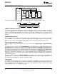
CLRB
CLRB must not be asserted here
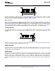
CSB
SCLK
1
2 2343 24
LDACB
LDACB must not transition here (may be
held low for whole transaction)
DAC161S055
www.ti.com
SNAS503B –NOVEMBER 2010–REVISED JANUARY 2012
The DAC Configuration command LDAC (see Section INSTRUCTION SET below) will also update the DAC
output as soon as it is received. The effect of hardware LDACB or software LDAC is the same i.e. data is
transferred from the PREREG to DACREG and output of the DAC is updated.
Write Commands
There are three write commands available in the DAC command set. Issuing a WR command causes the DAC to
update either the PREREG or the DACREG depending on the setting of the SWB bit (see Section Write-Through
and Write-Block Modes). Issuing a WRUP command causes the specified channels output (for multiple channel
parts) to update immediately, regardless of the SWB bit setting. Issuing a WRAL command causes all channels
(for multiple channel parts) to update immediately with the same data, regardless of the SWB bit setting.
CLEAR FUNCTION
The CLRB pin provides a easy way to reset the DAC161S055 output. If the CLRB pin goes low, VOUT
instantaneously slews to the value indicated by the MZB pin, either zero or midscale. The CLRB pin is level
sensitive.
Clear function can also be accessed via the software instruction CLR, see Section INSTRUCTION SET below.
The effect of hardware CLRB or software CLR is the same.
POWER ON RESET
An on-chip power on reset circuit (POR) ensures that the DAC always powers on in the same state. The
registers will be loaded with the defaults shown in Section INSTRUCTION SET. The output state will be
controlled by the state of the MZB pin.
POWER DOWN
Power down is achieved by writing the PD instruction and setting the appropriate bit to a logic '1'. In the PD
command, it is possible to specify if the output is left in a high impedance (HIZ) state or if it is pulled to GND
through a 10K resistor. During power down, the output amplifier is disabled and the resistor ladder is
disconnected from Vref. The SPI interface remains active. To exit power down, write the PD command again,
setting the appropriate bit to a logic '0'. Note that the SPI interface and the registers are all active during power
down.
Copyright © 2010–2012, Texas Instruments Incorporated Submit Documentation Feedback 17
Product Folder Links: DAC161S055