
Datasheet


bq24030, bq24031
bq24032A, bq24035, bq24038
www.ti.com
............................................................................................................................................... SLUS618H –AUGUST 2004–REVISED OCTOBER 2009
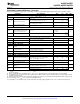
ELECTRICAL CHARACTERISTICS (continued)
over junction temperature range (0°C ≤ T
J
≤ 125°C) and the recommended supply voltage range (unless otherwise noted)
PARAMETER TEST CONDITIONS MIN TYP MAX UNIT
OUT PIN – FET (Q1, Q3, AND Q2) DROP-OUT VOLTAGE (RDSon)
V
I(AC)
≥ V
CC(min)
, PSEL = High, I
I(AC)
= 1 A,
V
(ACDO)
AC to OUT dropout voltage
(6)
300 475
(I
O(OUT)
+ I
O(BAT)
), or no AC
V
I(USB)
≥ V
CC(min)
, PSEL = Low, ISET2 = High,
140 180 mV
I
I(USB)
= 0.4 A, (I
O(OUT)
+I
O(BAT)
), or no AC
V
(USBDO)
(7)
USB to OUT dropout voltage
V
I(USB)
≥ V
CC(min)
, PSEL = Low, ISET2 = Low,
28 36
I
I(USB)
= 0.08 A, (I
O(OUT)
+ I
O(BAT)
)
BAT to OUT dropout voltage
V
(BATDO)
V
I (BAT)
≥ 3 V, I
i(BAT)
= 1.0 A, V
CC
< V
i(BAT)
40 100 mV
(discharging)
OUT PIN - BATTERY SUPPLEMENT MODE
Enter battery supplement mode V
I(OUT)
V
BSUP1
(battery supplements OUT current V
I(BAT)
> 2 V ≤ V
I(BAT)
in the presence of input source – 60 mV
V
V
I(OUT)
V
BSUP2
Exit battery supplement mode V
I(BAT)
> 2 V ≥ V
I(BAT)
– 20 mV
OUT PIN - SHORT CIRCUIT
Current source between BAT to OUT for short-circuit
I
OSH1
BAT to OUT short-circuit recovery 10 mA
recovery to V
I(OUT)
≤ V
I(BAT)
–200 mV
R
SHAC
AC to OUT short-circuit limit V
I(OUT)
≤ 1 V 500
Ω
R
SHVSB
USB to OUT short-circuit limit V
I(OUT)
≤ 1 V 500
BAT PIN CHARGING – PRECHARGE
Precharge to fast-charge transition
V
(LOWV)
Voltage on BAT 2.9 3 3.1 V
threshold
Deglitch time for fast-charge to t
FALL
= 100 ns, 10 mV overdrive,
T
DGL(F)
22.5 ms
precharge transition
(8)
V
I(BAT)
decreasing below threshold
1 V < V
I(BAT)
< V
(LOWV)
, t < t
(PRECHG)
,
I
O(PRECHG)
Precharge range 10 150 mA
I
O(PRECHG)
= (K
(SET)
× V
(PRECHG)
)/ R
SET
V
(PRECHG)
Precharge set voltage 1 V < V
I(BAT)
< V
(LOWV)
, t < t
(PRECHG)
230 250 270 mV
BAT PIN CHARGING - CURRENT REGULATION
V
i (BAT)
> V
(LOWV)
, V
I(OUT)
- V
I (BAT)
> V
(DO-MAX)
,
I
O(BAT)
AC battery charge current range
(9)
PSEL = High I
OUT(BAT)
= (K
(SET)
× V
(SET)
/ R
SET
), 100 1000 1500 mA
V
I
(OUT) > V
O
(OUT-REG) + V
(DO-MAX)
R
PBAT
BAT to OUT pullup V
i (BAT)
< 1 V 1000
Ω
AC to OUT and USB to OUT
R
POUT
V
I(OUT)
< 1 V 500
short-circuit pullup
Battery charge current set Voltage on ISET1, V
VCC
≥ 4.35 V,
V
(SET)
2.475 2.500 2.525 V
voltage
(10)
V
I(OUT)
- V
I(BAT)
> V
(DO-MAX)
, V
I(BAT)
> V
(LOWV)
100 mA ≤ I
O(BAT)
≤ 1 A 400 425 450
K
(SET)
Charge current set factor, BAT
10 mA ≤ I
O(BAT)
≤ 100 mA
(11)
300 450 600
(6) V
DO(max)
, dropout voltage is a function of the FET, R
DS(on)
, and drain current. The dropout voltage increases proportionally to the
increase in current.
(7) R
DS(on)
of USB FET Q3 is calculated by: (V
USB
– V
OUT
) / (I
OUT
+ I
BAT
) when I
I(USB)
≤ I
I(USB-MIN)
(FET fully on, not in regulation).
(8) All deglitch periods are a function of the timer setting and is modified in DPPM or thermal regulation modes by the percentages that the
program current is reduced.
(9) When input current remains below 2 A, the battery charging current may be raised until the thermal regulation limits the charge current.
(10) For half-charge rate, V
(SET)
is 1.25 V ± 25 mV for bq24032A/38 only.
(11) Specification is for monitoring charge current via the ISET1 pin during voltage regulation mode, not for a reduced fast-charge level.
Copyright © 2004–2009, Texas Instruments Incorporated Submit Documentation Feedback 5
Product Folder Link(s): bq24030, bq24031 bq24032A, bq24035, bq24038