
Datasheet


SLUS025F − MAY 2001 − REVISED JULY 2002
13
www.ti.com
APPLICATION INFORMATION
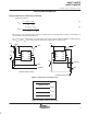
battery temperature monitoring (continued)
For PTC Thermistors
R
T1
+
5 R
TH
R
TC
3
ǒ
R
TH
* R
TC
Ǔ
R
T2
+
5 R
TH
R
TC
ƪ
ǒ
2 R
TH
Ǔ
–
ǒ
7 R
TC
Ǔ
ƫ
Where R
(TC)
is the cold temperature resistance and R
(TH)
is the hot temperature resistance of thermistor, as
specified by the thermistor manufacturer.
R
T1
or R
T2
can be omitted If only one temperature (hot or cold) setting is required. Applying a voltage between
the V
(TS1)
and V
(TS2)
thresholds to pin TS disables the temperature-sensing feature.
SNS
BAT
VCC
TS
COMP
CC
VSS
STAT
bq2057
DC+
DC−
BAT+
BAT−
SNS
BAT
VCC
TS
COMP
CC
VSS
STAT
bq2057
DC+
DC−
BAT+
BAT−
R
T1
Thermistor
High-Side Current Sensing
Thermistor
R
T2
R
T1
R
T2
R
SNS
Low-Side Current Sensing
R
SNS
Figure 9. Temperature Sensing Circuits
Temperature Fault
Normal Temperature Range
Temperature Fault
V
CC
V
(TS2)
V
(TS1)
V
SS
Figure 10. bq2057 TS Input Thresholds
(5)
(6)