
Datasheet


Configuring Algorithm and Display
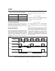
Modes
QSEL/LED
3
, DSEL/LED
2
, and TSEL/LED
1
are bi-
directional pins with two functions; they are LED driver
pins as outputs and programming pins for the bq2031 as
inputs. The selection of pull-up, pull-down, or no pull re
-
sistor programs the charging algorithm on QSEL and
TSEL per Table 1 and the display mode on DSEL per
Table 2. The bq2031 latches the program states when
any of the following events occurs:
1. V
CC
rises to a valid level.
2. The bq2031 leaves the Fault state.
3. The bq2031 detects battery insertion.
The LEDs go blank for approximately 750ms (typical)
while new programming data is latched.
For example, Figure 5 shows the bq2031 configured for
the Pulsed Current algorithm and display mode 2.
Voltage and Current Monitoring
The bq2031 monitors battery pack voltage at the BAT
pin. A voltage divider between the positive and negative
terminals of the battery pack is used to present a scaled
battery pack voltage to the BAT pin and an appropriate
value for regulation of float (maintenance) voltage to the
FLOAT pin. The bq2031 also uses the voltage across a
sense resistor (R
SNS
) between the negative terminal
of the battery pack and ground to monitor current.
See Figure 6 for the configuration of this network.
6
bq2031
FG203103.eps
bq2031
LED1/TSEL
V
CC
COM
LED3/QSEL
V
CC
V
SS
LED2/DSEL
16
15
13
12
11
10
10K 10K
1K
1K
1K
10K
V
SS
Figure 5. Configuring Charging Algorithm and Display Mode
FG203102.eps
bq2031
BAT
V
CC
SNS
V
CC
V
SS
FLOAT
2
3
13
12
7
RB3
BAT -
R
SNS
V
SS
BAT +
RB1
RB2
Figure 6. Configuring the Battery Divider