
Datasheet


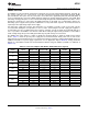

Table Of Contents
- FEATURES
- APPLICATIONS
- DESCRIPTION
- ABSOLUTE MAXIMUM RATINGS
- ELECTRICAL CHARACTERISTICS: Transmitter (Tx)
- ELECTRICAL CHARACTERISTICS: Power Amplifier (PA)
- ELECTRICAL CHARACTERISTICS: Receiver (Rx)
- ELECTRICAL CHARACTERISTICS: Digital
- ELECTRICAL CHARACTERISTICS: Two-Wire Interface
- ELECTRICAL CHARACTERISTICS: Internal Bias Generator
- ELECTRICAL CHARACTERISTICS: Power Supply
- THERMAL INFORMATION
- SPI TIMING REQUIREMENTS
- DEVICE INFORMATION
- TYPICAL CHARACTERISTICS
- APPLICATION INFORMATION
- Revision History

0.0
3.3
ZC
OUT
Time (5 ms/div)
0 50 100
350
0
-350
120 VAC to 240 VAC
50 Hz to 60 Hz
+
330 kW 330 kW 330 kW
120 VAC
to 240 VAC
50/60 Hz
ZLLS410 or
equivalent
ZLLS410 or
equivalent
AVDD
3.3 V
ZC
IN
ZC
OUT
AV
DD
AGND
Zero
Crossing
Inside the AFE031
AFE031
www.ti.com
SBOS531D –AUGUST 2010–REVISED MAY 2012
Zero Crossing Detector Block
The AFE031 includes two zero crossing detectors. Zero crossing detectors can be used to synchronize
communications signals to the ac line or sources of noise. Typically, in single-phase applications, only a single
zero crossing detector is used. In three-phase applications, both zero crossing detectors can be used; one
component detects phase A, and one detects phase B. Phase C zero crossings can then be inferred from the
data gathered from the other phases. Figure 38 shows the AFE031 configured for non-isolated zero crossing
detection.
Figure 38. Non-Isolated Zero Crossing Detection Using the AFE031
Non-isolated zero crossing waveforms are shown in Figure 39.
Figure 39. Non-Isolated Zero Crossing Waveforms
Copyright © 2010–2012, Texas Instruments Incorporated 31
Product Folder Link(s): AFE031