
Datasheet


CONVST
CONVST
CONVST
#1
#2
#3
EOC#1
(activelow)
CS #2
#3CS
SCLK#1
SCLK#2
SCLK#3
SDO#1
CDI#2
SDO#2
CDI#3
EOS
EOC
EOS
Conversion N
1..............16
ManualTrigger,ReadWhileSampling
(UseinternalCCLK,EOCactivelow,andTAGmodedisabled)
High-Z
High-Z
CS #1
t =18CCLK
CONV
t =3CCLKmin
SAMPLE1
t
SU2
t
SU2
SDO#3
1..............16 1..............16
Conversion
fromDevice#1
N
SDI#1
SDI#2
SDI#3
Don'tCare
Configure
ReadData ReadData
Don'tCare
t
WH1
t
WH1
t
WH1
t
WH1
Conversion
fromDevice#1
N Conversion
fromDevice#1
N
High-Z
High-Z
Conversion
fromDevice#2
N
Conversion
fromDevice#2
N Conversion
fromDevice#2
N
High-Z
High-Z
Conversion
fromDevice#3
N
Conversion
fromDevice#3
N Conversion
fromDevice#3
N
Don'tCare
Don'tCare
High-Z
High-Z
High-Z
High-Z
High-ZHigh-Z
ADS8331
ADS8332
www.ti.com
SBAS363C –DECEMBER 2009–REVISED MAY 2012
Case 1: If chip select is not toggled (CS stays low), the next 16 bits of data are from the upstream converter, and
so on. This configuration is shown in Figure 47.
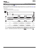
Case 2: If the chip select is toggled during a daisy-chain mode data transfer cycle, as illustrated in Figure 48, the
same data from the converter are read out again and again in all three discrete 16-bit cycles. This state is not a
desired result.
Figure 48. Simplified Daisy-Chain Mode Timing with Shared CONVST and Noncontinuous CS
Copyright © 2009–2012, Texas Instruments Incorporated 31