
Datasheet


ADS7950, ADS7951, ADS7952, ADS7953
ADS7954, ADS7955, ADS7956, ADS7957
ADS7958, ADS7959, ADS7960, ADS7961
www.ti.com
SLAS605A –JUNE 2008–REVISED JANUARY 2010
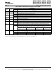
Table 6. Program Register Settings for Auto-2 Mode
DESCRIPTION
RESET
BITS
LOGIC
STATE
FUNCTION
STATE
DI15-12 NA 1001 Auto-2 program register is selected for programming
DI11-10 NA Do not care
DI09-06 NA aaaa This 4-bit data represents the address of the last channel in the scanning sequence. During device
operation in Auto-2 mode, the channel counter starts at CH-00 and increments every frame until it
equals “aaaa”. The channel counter roles over to CH-00 in the next frame.
DI05-00 NA Do not care
CONTINUED OPERATION IN A SELECTED MODE
Once a device is programmed to operate in one of the modes, the user may want to continue operating in the
same mode. Mode Control Register settings to continue operating in a selected mode are detailed in Table 7.
Table 7. Continued Operation in a Selected Mode
DESCRIPTION
RESET
BITS
LOGIC
STATE
FUNCTION
STATE
DI15-12 0001 0000 The device continues to operate in the selected mode. In Auto-1 and Auto-2 modes the channel
counter increments normally, whereas in the Manual mode it continues with the last selected
channel. The device ignores data on DI11-DI00 and continues operating as per the previous
settings. This feature is provided so that SDI can be held low when no changes are required in the
Mode Control Register settings.
DI11-00 All '0' Device ignores these bits when DI15-12 is set to 0000 logic state
PROGRAMMING ALARM THRESHOLDS
There are two Alarm Program Registers per channel, one for setting the high alarm threshold and the other for
setting the low alarm threshold. For ease of programming, two alarm programming registers per channel,
corresponding to four consecutive channels, are assembled into one group (a total eight registers). There are
four such groups for 16 channel devices and 3/2/1 such groups for 12/8/4 channel devices respectively. The
grouping of the various channels for each device in the ADS79XX family is listed in Table 8. The details
regarding programming the alarm thresholds are illustrated in the flowchart in Figure 55. Table 9 lists the details
regarding the Alarm Program Register settings.
Table 8. Grouping of Alarm Program Registers
GROUP NO. REGISTERS APPLICABLE FOR DEVICE
0 High and low alarm for channel 0, 1, 2, and 3 ADS7953..50, ADS7957..54, ADS7961..58
1 High and low alarm for channel 4, 5, 6, and 7 ADS7953..51, ADS7957..55, ADS7961..59
2 High and low alarm for channel 8, 9, 10, and 11 ADS7953 and 52, ADS7957 and 56, ADS7961 and 60
3 High and low alarm for channel 12, 13, 14, and 15 ADS7953, ADS7957, ADS7961
Each alarm group requires 9 CS frames for programming their respective alarm thresholds. In the first frame the
device enters the programming sequence and in each subsequent frame it programs one of the registers from
the group. The device offers a feature to program less than eight registers in one programming sequence. The
device exits the alarm threshold programming sequence in the next frame after it encounters the first ‘Exit Alarm
Program’ bit high.
Copyright © 2008–2010, Texas Instruments Incorporated Submit Documentation Feedback 35
Product Folder Link(s): ADS7950, ADS7951, ADS7952, ADS7953 ADS7954, ADS7955, ADS7956, ADS7957 ADS7958,
ADS7959, ADS7960, ADS7961