
Datasheet


ADS8363
ADS7263
ADS7223
SBAS523B –OCTOBER 2010–REVISED JANUARY 2011
www.ti.com
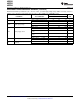
Pin Descriptions (continued)
PIN
NAME NO. TYPE
(1)
DESCRIPTION
Chip select. When this pin is low, the SDOx, SDI, and RD pins are active; when this pin is high, the
CS 21 DI
SDOx outputs are 3-stated, while the SDI and RD inputs are ignored.
External clock input. The range is 0.5MHz to 20MHz in half-clock mode, or 1MHz to 40MHz in
CLOCK 22 DI
full-clock mode.
Converter busy indicator. BUSY goes high when the inputs are in hold mode and returns to low after
BUSY 23 DO
the conversion is complete.
SDOB 24 DO Serial data output for converter B. Active only if M1 is low. 3-state when CS is high.
SDOA 25 DO Serial data output for converter A. 3-state when CS is high.
DVDD 27 P Digital supply, 2.3V to 5.5V. Decouple to DGND with a 1mF ceramic capacitor.
DGND 28 P Digital ground. Connect to digital ground plane.
CMA 31 AI Common-mode voltage input for channels Ax (in pseudo-differential mode only).
CMB 32 AI Common-mode voltage input for channels Bx (in pseudo-differential mode only).
8 Submit Documentation Feedback Copyright © 2010–2011, Texas Instruments Incorporated
Product Folder Link(s): ADS8363 ADS7263 ADS7223