
Datasheet


ADS131E08EVM Daughter-Card Hardware Overview
www.ti.com
3.3.2 Accessing ADS131E08 Digital Supplies
The ADS131E08 digital signals (including SPI signals, some GPIO signals, and some control signals) are
available at connector J1. These signals are used to interface to the MMB0 board DSP. The pinout for this
connector is shown in Table 7.
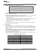
Table 7. Serial Interface Pinout
Signal J1 Pin Number Signal
START/CS 1 2 CLKSEL
CLK 3 4 GND
NC 5 6 GPIO1
CS 7 8 RESET
NC 9 10 GND
DIN 11 12 GPIO2
DOUT 13 14 NC/START
DRDY 15 16 SCL
EXT_CLK 17 18 GND
NC 19 20 SDA
3.4 Analog Inputs
The ADS131E08 provides users the option to feed in signals from any arbitrary signal source directly.
Analog signals can be applied at terminal blocks J5 through J12.
14
Performance Demonstration Kit for the ADS131E08 SBAU200–June 2012
Submit Documentation Feedback
Copyright © 2012, Texas Instruments Incorporated