
Datasheet


½H(f) =½
3
sin
N fp
f
MOD
N sin´
pf
f
MOD
½H(z) =½
3
1 Z-
- N
1 Z-
- 1
ADS1299
www.ti.com
SBAS499A –JULY 2012–REVISED AUGUST 2012
DIGITAL DECIMATION FILTER
The digital filter receives the modulator output and decimates the data stream. By adjusting the amount of
filtering, tradeoffs can be made between resolution and data rate: filter more for higher resolution, filter less for
higher data rates. Higher data rates are typically used in EEG applications for ac lead-off detection.
The digital filter on each channel consists of a third-order sinc filter. The sinc filter decimation ratio can be
adjusted by the DR bits in the CONFIG1 register (see the Register Map section for details). This setting is a
global setting that affects all channels and, therefore, all channels operate at the same data rate in a device.
Sinc Filter Stage (sinx / x)
The sinc filter is a variable decimation rate, third-order, low-pass filter. Data are supplied to this section of the
filter from the modulator at the rate of f
MOD
. The sinc filter attenuates the modulator high-frequency noise, then
decimates the data stream into parallel data. The decimation rate affects the overall converter data rate.
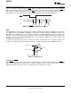
Equation 4 shows the scaled Z-domain transfer function of the sinc filter.
(4)
The frequency domain transfer function of the sinc filter is shown in Equation 5.
where:
N = decimation ratio (5)
Copyright © 2012, Texas Instruments Incorporated Submit Documentation Feedback 21
Product Folder Link(s): ADS1299