
Datasheet


2x
1x
1x
8x
AVDD
AVSS
TemperatureSensorMonitor
ToMUXTempP
ToMUXTempN
Temperature ( C) =°
Temperature Reading ( V) 145,300 Vm - m
490 V/ Cm °
+ 25 C°
ADS1299
www.ti.com
SBAS499A –JULY 2012–REVISED AUGUST 2012
Device Noise Measurements
Setting CHnSET[2:0] = 001 sets the common-mode voltage of [(VREFP + VREFN) / 2] to both channel inputs.
This setting can be used to test inherent device noise in the user system.
Test Signals (TestP and TestN)
Setting CHnSET[2:0] = 101 provides internally-generated test signals for use in sub-system verification at power-
up. This functionality allows the device internal signal chain to be tested out.
Test signals are controlled through register settings (see the CONFIG2: Configuration Register 2 subsection in
the Register Map section for details). TEST_AMP controls the signal amplitude and TEST_FREQ controls
switching at the required frequency.
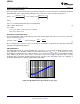
Temperature Sensor (TempP, TempN)
The ADS1299 contains an on-chip temperature sensor. This sensor uses two internal diodes with one diode
having a current density 16x that of the other, as shown in Figure 20. The difference in diode current densities
yields a voltage difference proportional to absolute temperature.
As a result of the low thermal resistance of the package to the printed circuit board (PCB), the internal device
temperature tracks PCB temperature closely. Note that self-heating of the ADS1299 causes a higher reading
than the temperature of the surrounding PCB.
The scale factor of Equation 1 converts the temperature reading to degrees Celsius. Before using this equation,
the temperature reading code must first be scaled to microvolts.
(1)
Figure 20. Temperature Sensor Measurement in the Input
Supply Measurements (MVDDP, MVDDN)
Setting CHnSET[2:0] = 011 sets the channel inputs to different supply voltages of the device. For channels 1, 2,
5, 6, 7, and 8, (MVDDP – MVDDN) is [0.5 × (AVDD + AVSS)]; for channels 3 and 4, (MVDDP – MVDDN) is
DVDD / 4. Note that to avoid saturating the PGA while measuring power supplies, the gain must be set to '1'.
Lead-Off Excitation Signals (LoffP, LoffN)
The lead-off excitation signals are fed into the multiplexer before the switches. The comparators that detect the
lead-off condition are also connected to the multiplexer block before the switches. For a detailed description of
the lead-off block, refer to the Lead-Off Detection subsection in the EEG-Specific Functions section.
Copyright © 2012, Texas Instruments Incorporated Submit Documentation Feedback 17
Product Folder Link(s): ADS1299