
Datasheet


Ch1
ADC
Modulation
Block
Demodulation
Block
RESP_CTRL[1:0]
Ch1
PGA
RespirationClock
Generator
CLK
I/O
I/O
I/O
RESP_CTRL[1:0]
GPIO3
GPIO4
GPIO2
RESP_MODP
RESP_MODN
IN1P
IN1N
EMI
Filter
MUX
Blocking
Demodulation
Clock
Modulation
Clock
Mod.Clock
ADS1294, ADS1294R
ADS1296, ADS1296R
ADS1298, ADS1298R
SBAS459I –JANUARY 2010–REVISED JANUARY 2012
www.ti.com
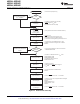
Internal Respiration Circuitry with Internal Clock (RESP_CTRL = 10b, ADS1294R/6R/8R Only)
Figure 67 shows a block diagram of the internal respiration circuitry. The internal modulation and demodulator
circuitry can be selectively used. The modulation block is controlled by the RESP_MOD_EN bit and the
demodulation block is controlled by the RESP_DEMOD_EN bit. The modulation signal is a square wave of
magnitude VREFP – AVSS. In this mode, the output of the modulation circuitry is available at the RESP_MODP
and RESP_MODN terminals of the device. This availability allows custom filtering to be added to the square
wave modulation signal. In this mode, GPIO2, GPIO3, and GPIO4 can be used for other purposes. The
modulation frequency can be 64kHz or 32kHz, as set by the RESP_FREQ[2:0] bits in the CONFIG4 register. The
phase of the internal demodulation signal is set by the RESP_PH[2:0] bits in the RESP register.
The ADS1294R/6R/8R channel 1 with respiration enabled mode cannot be used to acquire ECG signals. If the
RA and LA leads are intended to measure respiration and ECG signals, the two leads can be wired into channel
1 for respiration and channel 2 for ECG signals.
Figure 67. Internal Respiration Block Diagram
72 Submit Documentation Feedback Copyright © 2010–2012, Texas Instruments Incorporated
Product Folder Link(s): ADS1294 ADS1294R ADS1296 ADS1296R ADS1298 ADS1298R