
Datasheet


Converting Converting Converting Converting
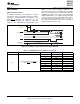
START
DOUT/DRDY
ADS1146/7/8
Status
DataReady DataReady DataReady
ADS1146
ADS1147
ADS1148
SBAS453F –JULY 2009–REVISED APRIL 2012
www.ti.com
The ADS1146/7/8 can be configured to convert transferred to the ADS1146/7/8, new settings become
continuously by holding the START pin high, as active at the end of each byte sent. Therefore, a brief
shown in Figure 36. With the START pin held high, overload condition can occur during the transmission
the ADC converts the selected input channels of configuration data after the completion of the
continuously. This configuration continues until the MUX0 byte and before the completion of the SYS0
START pin is taken low. byte. This temporary overload can result in
intermittent incorrect readings. To ensure that an
The START pin can also be used to perform the
overload does not occur, it may be necessary to split
synchronized measurement for the multi-channel
the communication into two separate communications
applications by pulsing the START pin.
allowing the change of the SYS0 register bfore the
change of the MUX0 register.
RESET
In the event of an overloaded state, care must also
When the RESET pin goes low, the device is
be taken to ensure single cycle settling into the next
immediately reset. All the registers are restored to
cycle. Because the ADS1146/7/8 implement a
default values. The device stays in reset mode as
chopper-stabilized PGA, changing data rates during
long as the RESET pin stays low. When it goes high,
an overload state can cause the chopper to become
the ADC comes out of reset mode and is able to
unstable. This instability results in slow settling time.
convert data. After the RESET pin goes high, and
To prvent this slow settling, always change the PGA
when the system clock frequency is 4.096MHz, the
setting or MUX setting to a non-overloaded state
digital filter and the registers are held in a reset state
bfore changing the data rate.
for 0.6ms when f
OSC
= 4.096MHz. Therefore, valid
SPI communication can only be resumed 0.6ms after
Single-Cycle Settling
the RESET pin goes high; see Figure 4. When the
RESET pin goes low, the clock selection is reset to
The ADS1146/7/8 are capable of single-cycle settling
the internal oscillator.
across all gains and data rates. However, to achieve
single-cycle settling at 2kSPS, special care must be
Channel Cycling and Overload Recovery
taken with respect to the interface. When operating at
2kSPS, the SPI data SCLK period must not exceed
When cycling through channels, care must be taken
520ns, and the time between the beginning of a byte
when configuring the ADS1146/7/8 to ensure that
and the beginning of a subsequent byte must not
settling occurs within one cycle. For setups that
exceed 4.2µs. Additionally, when performing multiple
simply cycle through MUX channels, but do not
individual write commands to the first four registers,
change PGA and data rate settings, simply changing
wait at least 64 oscillator clocks before initiating
the MUX0 register is sufficient. However, when
another write command.
changing PGA and data rate settings it is important to
ensure that an overloaded condition cannot occur
during the transmission. When configuration data are
NOTE: SCLK held low in this example.
Figure 36. Timing for Conversion with START Pin High
28 Submit Documentation Feedback Copyright © 2009–2012, Texas Instruments Incorporated
Product Folder Link(s): ADS1146 ADS1147 ADS1148