
Datasheet


www.ti.com
ADS1000 I
2
C ADDRESSES
I
2
C GENERAL CALL
REGISTERS
OUTPUT REGISTER
I
2
C DATA RATES
ADS1000
SBAS357A – SEPTEMBER 2006 – REVISED OCTOBER 2007
mode must be activated. To activate High-speed
mode, send a special address byte of 00001XXX
The ADS1000 I
2
C address is either 1001000 or
following the start condition, where the XXX bits are
1001001, set at the factory. The address is identified
unique to the Hs-capable master. This byte is called
with an A0 or an A1 within the orderable name.
the Hs master code. (Note that this is different from
The two different I
2
C variants are also marked normal address bytes; the low bit does not indicate
differently. Devices with an I
2
C address of 1001000 read/write status.) The ADS1000 will not
have packages marked BD0, while devices with an acknowledge this byte; the I
2
C specification prohibits
I
2
C address of 1001001 are marked with BD1. See acknowledgment of the Hs master code. On receiving
the Package/Ordering Information Table for a a master code, the ADS1000 will switch on its
complete listing of the ADS1000 I
2
C addresses and High-speed mode filters, and will communicate at up
tape and reel size. to 3.4MHz. The ADS1000 switches out of Hs mode
with the next stop condition.
For more information on High-speed mode, consult
The ADS1000 responds to General Call Reset, which the I
2
C specification.
is an address byte of 00h followed by a data byte of
06h. The ADS1000 acknowledges both bytes.
On receiving a General Call Reset, the ADS1000 The ADS1000 has two registers that are accessible
performs a full internal reset, just as though it had via its I
2
C port. The output register contains the result
been powered off and then on. If a conversion is in of the last conversion; the configuration register
process, it is interrupted; the output register is set to allows users to change the ADS1000 operating mode
zero, and the configuration register returns to its and query the status of the device.
default setting.
The ADS1000 always acknowledges the General Call
address byte of 00h, but it does not acknowledge any The 16-bit output register contains the result of the
General Call data bytes other than 04h or 06h. last conversion in binary two ’ s complement format.
Since the port yields 12 bits of data, the ADS1000
outputs right-justified and sign-extended codes. This
output format makes it possible to perform averaging
The I
2
C bus operates in one of three speed modes:
using a 16-bit accumulator.
Standard, which allows a clock frequency of up to
100kHz; Fast, which allows a clock frequency of up to Following reset or power-up, the output register is
400kHz; and High-speed mode (also called Hs cleared to '0'; it remains zero until the first conversion
mode), which allows a clock frequency of up to is completed. Therefore, if a user reads the ADS1000
3.4MHz. The ADS1000 is fully compatible with all just after reset or power-up, the output register will
three modes. read '0'.
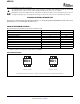
No special action needs to be taken to use the The output register format is shown in Table 2 .
ADS1000 in Standard or Fast modes, but High-speed
Table 2. OUTPUT REGISTER
BIT 15 14 13 12 11 10 9 8 7 6 5 4 3 2 1 0
NAME D15
(1)
D14
(1)
D13
(1)
D12
(1)
D11 D10 D9 D8 D7 D6 D5 D4 D3 D2 D1 D0
(1) D15 – D12 are sign extensions of 12-bit data.
8 Submit Documentation Feedback Copyright © 2006 – 2007, Texas Instruments Incorporated
Product Folder Link(s): ADS1000