
User's Manual


Section 3 – General System Information
11
3-1. General System Information.
The Telemotive Radio Control System (system)
provides remote control of overhead cranes using
radio signals. The system consists of a hand held
portable battery operated transmitter unit and a fixed
station receiver unit.
A unique 16-bit code (Access Code) for each system
is preset in every transmitter and receiver. The
receiver considers any received signal, which does
not match the receiver access code setting, invalid.
The Access Code is made up of 16-bits (65,000
combinations) and no two similar codes are assigned
to any two Telemotive systems.
Up to four systems may be used with the same
frequency in a 600-foot area (220 meters). Each
transmitter operating on the same frequency may be
operated in close proximity, not less than six feet (1.9
meters), to each other.
3-2. TMS Low Power Signaling.
TMS (Time Multiplexed Signaling) is a Telemotive
proprietary high-speed packet data system. The
system software is structured to minimize "on the air"
transmission time of any transmitter. This allows for
multiple transmitters to share a common frequency.
The TMS system is designed so that a transmitter will
send a signal for a predetermined ON time, and then
will turn OFF. The length of transmitter ON time is
referred to as data burst or packet. The packet length
is a function of the quantity of data to be sent, and the
data rate (baud). Once the packet is sent, the
transmitter will turn OFF. This allows for other
transmitters to time-share the same frequency when a
transmitter has turned OFF. The TMS system soft-
ware determines the OFF period and repetition rate of
the ON period. Since each system has its own access
code, up to 4 transmitters can share and have equal
access to the same frequency. TMS also allows for
reduced battery consumption and extended battery
life.
These systems have low power pulsed signaling,
FCC certified under Part 15 Telecommunications
Code of Regulations, no license is required. The
transmitter unit is frequency modulated, low power
and is certified under the appropriate regulations. A
license is not required for the transmitter or operator.
Modifications to the RF section of this system are not
permitted and could void FCC certification.
Active ESTOP (optional), this feature causes the
transmitter to send confirmation that the ESTOP is
not being engaged via a periodic confirmation signal.
Units so equipped will shut down the receiver when
out of range.
3-3. Channel Designations:
AK01 - 439.8 MHz AK06 - 438.8 MHz
AK02 - 439.6 MHz AK07 - 438.6 MHz
AK03 - 439.4 MHz AK08 - 438.4 MHz
AK04 - 439.2 MHz AK09 - 438.2 MHz
AK05 - 439.0 MHz AK10 - 438.0 MHz
AK11 - 437.8 MHz AK16 - 436.8 MHz
AK12 - 437.6 MHz AK17 - 436.6 MHz
AK13 - 437.4 MHz AK18 - 436.4 MHz
AK14 - 437.2 MHz AK19 - 436.2 MHz
AK15 - 437.0 MHz AK20 - 436.0 MHz
AKA00 - 433.125 MHz AKA05 - 434.125 MHz
AKA01 - 433.325 MHz AKA06 - 434.325 MHz
AKA02 - 433.525 MHz AKA07 - 434.525 MHz
AKA03 - 433.725 MHz AKA08 - 434.725 MHz
AKA04 - 433.925 MHz
3-4. Transmitter Specifications.
Transmitter housing: NEMA 4.
Operating Temperature: –22° F to +158° F (-30º C to
+70º C) ambient.
Humidity: up to 95 % (non-condensing).
Typical Operating Range: 200 feet (70 meters).
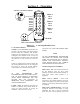
3-5. Transmitter Unit.
The transmitter is battery operated, has an ON and
OFF switch, E-STOP, motor controls and auxiliary
controls used for such item warning indicators.
LED’s mounted on the front panel provide indication
of battery voltage, ON/OFF, Modes and data
transmission status.
A power down feature allows the transmitter and the
receiver unit to turn OFF if no keys are pressed for
predetermined number of minutes. The transmitter
unit must again be turned ON. The unit uses pulsed
operation for extremely long battery life. A
configuration of the system is available without
automatic timeout.
Housings are designed of high impact, chemical
resistant, materials. The antenna for the unit is
internal. A strap is provided for carrying the
transmitter.