
User manual


Locking Clip Contacts and Housings
114- 25006
Rev F 3 of 9Tyco Electronics Corporation
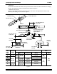
If the post is longer than the maximum specified, the post tip might butt against the wire.
2.54 x 2.54
[.100 x .100]
Figure 3
0.64--mm [.025--in.] (+0.03 [+.001]) Squar e Post
with Maximum Corner Radius of 0.08 [.003]
5.08--7.04 [.200--.277]
(Without Housing)
6.93--8.89
[.273--.350]
(With Housing)
Note: Not to Scale
3.4. Terminated Conductor Requirements
A.
Carrier Cutoff Tab and Burr
Cutoff tabs are the remaining portion of the carrier strip after the contact is cut off. The cutoff tab and burr
shall not exceed the dimensions given in Figure 4.
B. Wire Barrel Crimp
1. Crimp Dimensions
The wire barrel must be measured for crimp height and width. The wire barrel crimp height and width are
provided in Figure 4.
2. Tensile Strength
The wire must be retained in the contact wire barrel within the tensile strength pull force listed in
Figure 4.
3. Wire Conductor Location
After crimping, the end of the wire conductor must be flush with the front end of wire barrel or slightly
extended. Both insulation and conductor must be visible between the insulation barrel and wire barrel.
The maximum allowable wire conductor protrusion is given in Figure 4.
DO NOT crimp insulation in the wire barrel.
4. Wire Barrel Seam
Wire barrel seam must be completely closed and with no evidence of loose wire or wire strands visible in
the seam. See Figure 4.
5. Wire Barrel Flash
Wire barrel flash is the formation that may appear on both sides of the wire barrel as the result of the
crimping process. It must not exceed the limit shown in Figure 4.
NOTE
i
CAUTION
!