
User manual


Locking Clip Cont acts and Housings 114- 25006
Rev F2 of 9 Tyco Electronics Corporation
2. REFERENCE MATERIAL
2.1. Revision Summary
This paragraph is reserved for a revision summary of changes and additions made to this specification. The
following changes were made for this revision.
S Updated document to corporate requirements
S New logo and format
2.2. Customer Assistance
Reference Part Number 87124 and Product Code 5403 are representative numbers of Locking Clip 0.64--mm
[.025--in.] Square Contacts and Housings. Use of these numbers will identify the product line and expedite your
inquiries through a service network established to help you obtain product and tooling information. Such
information can be obtained through a local Tyco Electronics Representative or , after purchase, by calling the
Tooling Assistance Center number at the bottom of page 1.
2.3. Drawings
Customer Drawings for product part numbers are available from the service network. The information
contained in Customer Drawings takes priority if there is a conflict with this specification or with any other
technical documentation supplied by T yco Electronics.
2.4. Instructional Material
The following list includes instruction sheets (408--series) that provide assembly procedures for product,
operation, maintenance and repair of tooling, as well as setup and operation procedures of applicators; and
customer manuals (409--series) that provides setup, operation, and maintenance of machines.
408--7443 Hand Crimping Tool 90289--1
408--7604 Extraction Tool 91084--1
408--7627 Hand Crimping Tool 90295--1
408--8040 Quick--Change Applicator 466721--2
408--9388 Hand Crimping Tool 90431--1
409--5128 AMP--O--LECTRIC* Model “K” Terminating Machine 565435--5
3. REQUIREMENTS
3.1. Storage
The heat limitation for the contacts and housings is --65_ to 105_C[--85_ to 221_F].
The contacts and housings should remain in the shipping containers until ready for use to prevent damage to
the contact and housings. The contacts and housings should be used on a first in, first out basis to avoid
storage contamination that could adversely affect signal transmissions. The contacts have a shelf life of two
years from date of manufacture.
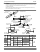
WIRE SIZE
(AWG)
INSULATION
DIAMETER
RECOMMENDED
STRIP LENGTH
20 1.27--2.54
[.050--.100]
3.96
[.156]
Strip
26--22 0.97--1.57
[.038--.062]
[
]
p
Length
Note: Not to Scale
30--28 0.74--0.99
[.029--.039]
3.81
[.150]
Figure 2
3.2. Wire Preparat ion
The contacts are designed to be used with discrete solid--conductor wire or stranded wire. The wire insulation
must be stripped according to dimensions in Figure 2.
3.3. Square Posts
The centerline spacing between adjacent posts and the functional length of the posts for installing contacts with
and without housing is shown in Figure 3.