
Datasheet


105
Catalog 1307819 Dimensions are in inches and Dimensions are shown for USA: 1-800-522-6752 South America: 55-11-2103-6000
Revised 8-08 millimeters unless otherwise reference purposes only. Canada: 1-905-470-4425 Hong Kong: 852-2735-1628
specified. Values in brackets Specifications subject Mexico: 01-800-733-8926 Japan: 81-44-844-8013
www.tycoelectronics.com are metric equivalents. to change. C. America: 52-55-1106-0803 UK: 44-8706-080-208
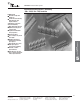
Breakaway Headers—Unshrouded, Double-Row,
.100 x .100 [2.54 x 2.54] Centerline
(Continued)
AMPMODU Interconnection System
Note: All part numbers are RoHS compliant.
Breakaway and Retention
Headers-Unshrouded
5
.025 [0.64] Square
Right-Angle Posts
A
D
E Ref.
(Contact
Area)
.100
[2.54]
B
.238
[6.05]
.042
[1.07]
(2 Plc.)
.090
[2.29]
Material and Finish
Housing — Black thermoplastic, 94V-0
rated, high temperature compatible
Posts — Phosphor bronze, duplex
plated .000030 [0.00076] gold on
contact area, .000100-.000200
[0.00254-0.00508] tin on solder tail,
with entire post underplated .000050
[0.00127] nickel
Performance Characteristics
(Board Retention Tails)
Insertion Force — 12 lb [53.4N] max.
Retention Force — .25 lb [1.11N] min.
Related Product Data
Mateable Connectors —
Refer to the Mating Post Selection
Guide — page 90
Technical Documents — page 276
See mating connector for applicable
product and application specifications.
.100
[2.54]
Ty p.
.140
[3.56]
*±.003 [±0.08] tolerances not to accumulate within one connector pattern.
Headers with Solder Tails
Recommended PC Board Mounting Pattern
(for .062 [1.57] thick PC board; .008 [.203] thick stencil)
Headers with Board Retention Tails
.045
[1.14]
Ref.
.090±.002
[2.29±0.05]
.030±.002
[0.76±0.05]
.035±.003
[0.89±0.08]
Dia. Typ.
(Plated)
Recommended Hole Size
Before Plating
.045±.001
[1.14±0.02]
Dia. Typ.
D
.090
[2.29]
.140
[3.56]
E Ref.
(Contact
Area)
A
B
.238
[6.05]
.042
[1.07]
(2 Plc.)
.100*
[2.54]
.075
[1.91]
Ty p.
.030±.002
[0.76±0.05]
.040±.003
[1.02±0.08]
Dia. Typ.
(Plated)
Recommended Hole Size
Before Plating
.045±.001
[1.14±0.02]
Dia. Typ.
.150±.002
[3.81±0.05]
*±.003 [±0.08] tolerances not to accumulate within one connector pattern.
Recommended PC Board Mounting Pattern
(for .062 [1.57] thick PC board; .008 [.203] thick stencil)
C = .120 [3.05] C = .110 [2.79]
Header No. of
Dimensions D = .230 [5.84] D = .318 [8.08]
Style Pos. A B
E = .185 [4.70] E = .200 [5.08]
Part Nos. Part Nos.
With
— 5-146308-1 5-146309-1
Solder Tails
2 .084 [2.13]
(See Notes
80 9-146308-0 9-146309-0
1 and 2.)
3.984 [101.19] 3.900 [99.06]
With Board
— 5-146310-1 5-146311-1
Retention Tails
2 .084 [2.13]
(See Note 2.)
80 9-146310-0 9-146311-0
3.984 [101.19] 3.900 [99.06]
Notes: 1. Headers without retention tails may be broken to the desired number of positions using Tool Kit No. 314818-1 (not shown).
Notes: 2. Headers are also available in sizes 4 thru 78 positions. When ordering, add the prefix and/or suffix (dash) numbers plus 5- -0 to
the base part number that corresponds with the number of positions per row. For example, the complete part number for a 16-
position header with solder tails (C dimension .120 [3.05)] would be 5-146308-8. The complete part number for a 40-position header
with board retention tails (C dimension .120 [3.05]) would be 7-146310-0. This part numbering system applies only to this page.
Board Retention
using Swaged Tails
(All Header Sizes)
.100
[2.54]
.100*
[2.54]
.100
[2.54]
.110
[2.79]
( of Stencil Pattern)
C
L
( of Hole Pattern)
C
L
.100
[2.54]
.100
[2.54]
( of
Hole
Pattern)
C
L
.170
[4.32]
( of Stencil Pattern)
C
L
.100
[2.54]
C
C