
Datasheet


114- 2161
Rev F 7 of 19
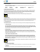
F. Tensile Strength
Crimped terminals or splices must hold the wire firmly and have a crimp pull--out test value meeting that
specified in Figure 4.
Adjust tensile testing machine for head travel of 25.4 [1.0] per minute. Directly and gradually apply force for one
minute.
WIRE SIZE (AWG)
TENSILE FORCE
(N [lb]) Min
26 13.4 [3]
24 22.3 [5]
22 35.6 [8]
20 57.9 [13]
18 89.0 [20]
16 133.5 [30]
14 222.5 [50]
12 311.5 [70]
10 356.0 [80]
8 400.5 [90]
6 445.0 [100]
4 623.0 [140]
2 801.0 [180]
1/0 11 12.5 [250]
2/0 1235.0 [300]
F
i
gu
r
e4
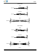
G. Bend Allowance
The force applied during crimping may cause some bending between the wire barrel and wire. Such
deformation is acceptable within the following limits.
1. Up and Down
The crimped portion must not be bent beyond the limits shown in Figure 5.
2. Side--to--Side
The crimped portion must not be bent from one side to the other beyond the limits shown in Figure 5.
3.8. Repair
Damaged terminals and splices or terminals and splices that do not meet crimp dimension requirements must
be removed from wires, discarded, and replaced with new ones. When removing a terminal or splice, cut the
wires as close as possible to the end of the wire barrel.
4. QUALIFICATION
PLASTI--GRIP terminals and splices are Listed by Underwriters Laboratories Inc. (UL) in File E13288, and
Certified by CSA International in File LR7189; except multi stud ring, ring tongue bent 90_, and tube cap
terminals.
NOTE
i