
Information


114-13065
9 of 10
Rev C
NOTE
Single row plug assemblies are keyed by the location of the plug latching fingers. TPA fingers go on top of the contacts. Dual
row plug assemblies have a “V” shaped notch inside the housing keys with a matching “V” shaped rib on the bottom of the TPA.
2. Push the TPA into the pre-staged position by hand. Verify the correct position by using the procedure
indicated in Paragraph 3.3.A.1.
3. Finish the assembly performing the remaining steps referring to in Paragraphs 3.3.A.2 through 3.3.A.7.
Re-assembly of the cap after servicing a contact should be performed as follows:
1. Align the keying features of the TPA with the appropriate features in the cap housings and place the
TPA locking fingers inside the cap housing. See Figure 11.
NOTE
Single row plug assemblies are keyed by the location of the plug latching fingers. TPA fingers go on top of the contacts. Dual
row plug assemblies have a “V” shaped notch inside the housing keys with a matching “V” shaped rib on the bottom of the TPA.
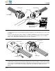
2. Push the TPA into the pre-staged position by using a screwdriver or equivalent with a blade as
described in Figure 12. Verify the correct position by using the procedure indicated in Paragraph 3.3.A.1.
3. Finish the assembly performing the remaining steps referring to in Paragraphs 3.3.A.2 through 3.3.A.7.
D. Peripheral Seal Replacement
The peripheral seal can be replaced when the connector is separated for servicing. Replacement of the seal
should be done as follows:
1. Separate the connector system and remove the TPA from the plug assembly using the procedure listed
in Paragraphs 3.3.B.1 through 3.3. B.3.
2. The old seal may now be removed by sliding it off the end of the plug housing.
3. The sealing surface of the plug housing should be cleaned to remove any dirt, moisture, or debris that
may be on the connector assembly.
4. The new seal may be assembled to the plug assembly by sliding it on the end of the plug housing.
CAUTION
Care should be taken to make sure the seal does not roll during this process.
5. Reassemble the TPA to the plug housing using the appropriate steps outlined in Paragraph 3.3.C.
CAUTION
Damaged product should not be used. If a damaged product is evident, it should be replaced with a new one.
4. QUALIFICATIONS
The AMPSEAL 16 Connector System is not required to be agency approved.
5. TOOLING
Refer to Application Specification 114-13045 for references on all pin and socket contact termination tooling.
Figure 12
NOTE
i
NOTE
i
!
!
Notch
12A
12B
6.0 x 1.0 [.236 x .039] (# 10)
Blade Tip Typ
Contact/TPA Removal Tool 776441-1
Screwdriver to Reseat Cap TPA