
Information


Product Specification
108-5262
Rev. C6 7 of 14
Para.
Test Items Requirements Procedures
3.5.9
Insulation Resistance
100MΩ min. (Initial)
Measure by applying test potential
between the adjacent contacts, and
between the contacts and ground in
the mated connectors.
Connector must withstand
test potential of 1.0kVAC for 1
minute. No physical damage
shall be evident after the test.
Measure by applying test potential
between the adjacent contacts, and
between the contacts and ground in
the mated connector. Fig.3.
3.5.10
Dielectric Strength
Fig.3
3.5.11
Handling Ergonomics No abnormal touch shall be
perceived during mating/
unmating, that may cause
pain or fatigue on separator’s
hand.
Repeat mating and unmating of
connectors by hands.
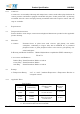
Wire Size Crimp Tensile
mm
2
(AWG)
N Min
0.2 (#24) 68.6
0.3 (#22) 78.5
0.5 (#20) 88.3
0.85 (#18) 127
3.5.12
Crimp Tensile
Strength
1.25 (#16) 177
Apply an axial pull-off load to
crimped wire of contact secured on
the tester, at a rate of 100mm (4.0”)
a minute.
TE Spec. 109-5205
3.5.13
Contact Retention
Force
Contact shall not dislodge a
distance greater than 78.5N
Min.
Apply an axial load to 0.85mm
2
,
100mm long crimped contact on
housing. Measure the force required
to dislodge the contact from housing.
TE Spec. 109-30