
Information


114- 40030
Rev D 5 of 13
3.3. Contact Insertion
Terminated contacts are inserted into the back of the connector housing, and snap in place. The cavity rows
are numbered for your convenience. If your design does not require the use of all cavities, the contacts should
be distributed evenly throughout the connector.
After inserting a contact into the housing, pull back lightly on the wire to make sure the contact is fully seated.
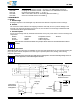
3.4. Terminated Strip Length
Terminated strip length shall be as indicated in Figure 3.
Figure 3
Ferrule
Braid
Connector
Terminated
Strip Length
B+
1.27 [.050]
TERMINATED STRIP LENGTH
CONTACT POSN “B” LENGTH
9
15
25
37
50
39.12 [1.540]
38.1 [1.500]
33.02 [1.300]
3.5. Ferrule Cr imp Requirements
Slide the ferrule onto the cable prior to stripping the cable. Keep the larger diameter end of the ferrule toward
the end to be terminated. If the ferrule has only one diameter, no orientation is required. After the wires and
contacts have been terminated slide the ferrule until it is over the braid. Crimp the braid according to the
instructions packaged with the appropriate tooling. See Figure 4 for ferrule crimp requirements.
Trim excess braid flush with front of ferrule with a knife.
Figure 4 (cont’d)
1.02 [.040] Max
D
D
E
E
F+0.64 [.025]
TERMINATED ASSY LEN GTH
CONTACT POSN “F” LENGTH
9
38.99 [1.535]
15
25
37
50
48.06 [1.892]
47.65 [1.876]
C
0.38 [.015] Max
BMax
A
Section D--D
Section E--E
NOTE
i
NOTE
i