
Datasheet


93
Catalog 82012 Dimensions are shown for Dimensions are in inches Canada: +1 (905) 475-6222 UK: +44 (0) 800-267666
Revised 4-12 reference purposes only. and millimeters unless Mexico/C. Am.: +52 (0) 55-1106-0800 France: +33 (0) 1-3420-8686
Specifications subject otherwise specified. Latin/S. Am.: +54 (0) 11-4733-2200 Netherlands: +31 (0) 73-6246-999
www.te.com to change. USA: +1 (800) 522-6752 Germany: +49 (0) 6251-133-1999 China: +86 (0) 400-820-6015
Ribbon Cable Interconnect Solutions
Military, Center and Dual Polarized
Universal Ejection Style Pinless Headers
Universal Ejection Style Pinless Headers, Military, Center
and Dual Polarized, .100 x .100 [2.54 x 2.54] Centerlines
(Continued)
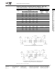
Installation of Press-Fit
Pinless Headers
Insertion Instructions:
1. Place pinless header
over preinstalled posts
so that post tips start into
header cavities.
2
. With bottom of pc board
supported, place steel
block over header. Steel
block must be wider and
longer than header so
that it covers all four sides
of the header. However,
for headers with latches
pre-assembled, the steel
block must not interfere
with the latches.
3. Apply an even, centered
force on steel block until
header bottoms on pc
board. If posts are longer
than .545 [13.84], they
may be forced against
the steel block before the
header is fully seated. In
this situation, extreme
caution must be taken so
that posts are not dam-
aged or pushed out of
the pc board.
Insertion Force: 60 lb. [267 N] max.
Retention Force: 20 lb. [89 N] min.
TE recommends the use of a typical manual frame assembly for insertion of
pinless headers.The frame assembly and steel block are not supplied by TE.
Steel Block
(Centered over
H
eader)
.529
[13.44]
.025
[0.64]
P
reinstalled in
PC Board
Sq. Posts
F
ORCE
PC Board
FORCE
Pinless Header