
IOM SYSLOOP (IOM SL 01 S 3GB)


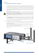

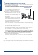
Table Of Contents
- CONTENTS
- 1. GENERAL RECOMMENDATIONS
- 2. INSPECTION AND STORAGE
- 3. WARRANTY
- 4. CONTENTS Of PACKAGE
- 5. DIMENSIONS
- 6. HANDLING
- 7. REFRIGERATION SPECIFICATIONS
- 8. TECHNICAL SPECIFICATIONS
- 9. ELECTRIC SPECIFICATIONS
- 10. INSTALLATION
- 11. DUCTING AND NOISE LEVEL REDUCTION
- 12. UNCLAMPING THE COMPRESSOR
- 13. HYDRAULIC LINKS
- 14. WIRING DIAGRAM AND LEGEND
- 15. ELECTRICAL CONNECTIONS
- 16. REGULATION
- 17. FINAL TASKS
- 18. STARTING - RECOMMENDATIONS - SETTINGS
- 19. MAINTENANCE AND SERVICING
- 19.1. FAULT FINDING
- 19.1.1. NEITHER THE FAN NOR THE COMPRESSOR OPERATE
- 19.1.2. VENTILATION (FAN) MODE OPERATES BUT THE COMPRESSOR DOES NOT OPERATE
- 19.1.3. INSUFFICIENT COOLING OR HEATING PRODUCTION
- 19.1.4. INSUFFICIENT WATER FLOW AT THE LEVEL OF THE COAXIAL EXCHANGER.
- 19.1.5. APPEARANCE OF WATER DROPLETS IN THE APPLIANCE
- 19.1.6. APPEARANCE OF ABNORMAL NOISES AND VIBRATIONS IN THE CASING
- 19.2. ALARM CODES
- 19.1. FAULT FINDING
- 20. IN CASE OF WARRANTY - MATERIAL RETURN PROCEDURE
- 21. ORDERING SERVICE AND SPARE PARTS ORDER
- DIMENSIONS
- CONFIGURATION R1.AI RECT/S4.AO RECT
- CONFIGURATION R2.AI RECT/S4.AO RECT
- CONFIGURATION R1.AI 1Ø200/S4.AO RECT OR R1.AI 1Ø200 FAØ100/S4.AO RECT OR R1.AI 1Ø200 FAØ125/S4.AO RECT
- CONFIGURATION R2.AI 1Ø200/S4.AO RECT OR R2.AI 1Ø200 FAØ100/S4.AO RECT OR R2.AI 1Ø200 FAØ125/S4.AO RECT
- CONFIGURATION R1.AI RECT/S4.AO 1Ø200 OR R1.AI RECT/S3.AO 1Ø200
- CONFIGURATION R2.AI RECT/S4.AO 1Ø200 OR R2.AI RECT/S3.AO 1Ø200
- CONFIGURATION R1.AI 1Ø200/S4.AO 1Ø200 OR R1.AI 1Ø200 FAØ100/S4.AO 1Ø200 OR R1.AI 1Ø200 FAØ125/S4.AO 1Ø200 OR R1.AI 1Ø200/S3.AO 1Ø200 OR R1.AI 1Ø200 FAØ100/S3.AO 1Ø200 OR R1.AI 1Ø200 FAØ125/S3.AO 1Ø200
- CONFIGURATION R2.AI 1Ø200/S4.AO 1Ø200 OR R2.AI 1Ø200 FAØ100/S4.AO 1Ø200 OR R2.AI 1Ø200 FAØ125/S4.AO 1Ø200 OR R2.AI 1Ø200/S3.AO 1Ø200 OR R2.AI 1Ø200 FAØ100/S3.AO 1Ø200 OR R2.AI 1Ø200 FAØ125/S3.AO 1Ø200
- CONFIGURATION AO XLN
- WIRING DIAGRAM
- DIMENSIONS
- CONFIGURATION R1.AI RECT/S4.AO RECT
- CONFIGURATION R2.AI RECT/S4.AO RECT
- CONFIGURATION R1.AI 1Ø200/S4.AO RECT OU R1.AI 1Ø200 FAØ100/S4.AO RECT OU R1.AI 1Ø200 FAØ125/S4.AO RECT
- CONFIGURATION R2.AI 1Ø200/S4.AO RECT OU R2.AI 1Ø200 FAØ100/S4.AO RECT OU R2.AI 1Ø200 FAØ125/S4.AO RECT
- CONFIGURATION R1.AI RECT/S4.AO 1Ø200 OU R1.AI RECT/S3.AO 1Ø200
- CONFIGURATION R2.AI RECT/S4.AO 1Ø200 OU R2.AI RECT/S3.AO 1Ø200
- CONFIGURATION R1.AI 1Ø200/S4.AO 1Ø200 OU R1.AI 1Ø200 FAØ100/S4.AO 1Ø200 OU R1.AI 1Ø200 FAØ125/S4.AO 1Ø200 OU R1.AI 1Ø200/S3.AO 1Ø200 OU R1.AI 1Ø200 FAØ100/S3.AO 1Ø200 OU R1.AI 1Ø200 FAØ125/S3.AO 1Ø200
- CONFIGURATION R2.AI 1Ø200/S4.AO 1Ø200 OU R2.AI 1Ø200 FAØ100/S4.AO 1Ø200 OU R2.AI 1Ø200 FAØ125/S4.AO 1Ø200 OU R2.AI 1Ø200/S3.AO 1Ø200 OU R2.AI 1Ø200 FAØ100/S3.AO 1Ø200 OU R2.AI 1Ø200 FAØ125/S3.AO 1Ø200
- CONFIGURATION AO XLN
- SCHEMAS ELECTRIQUES
- ABMESSUNGEN
- KONFIGURATION R1.AI RECT/S4.AO RECT
- KONFIGURATION R2.AI RECT/S4.AO RECT
- KONFIGURATION R1.AI 1Ø200/S4.AO RECT ODER R1.AI 1Ø200 FAØ100/S4.AO RECT ODER R1.AI 1Ø200 FAØ125/S4.AO RECT
- KONFIGURATION R2.AI 1Ø200/S4.AO RECT ODER R2.AI 1Ø200 FAØ100/S4.AO RECT ODER R2.AI 1Ø200 FAØ125/S4.AO RECT
- KONFIGURATION R1.AI RECT/S4.AO 1Ø200 ODER R1.AI RECT/S3.AO 1Ø200
- KONFIGURATION R2.AI RECT/S4.AO 1Ø200 ODER R2.AI RECT/S3.AO 1Ø200
- KONFIGURATION R1.AI 1Ø200/S4.AO 1Ø200 ODER R1.AI 1Ø200 FAØ100/S4.AO 1Ø200 ODER R1.AI 1Ø200 FAØ125/S4.AO 1Ø200 ODER R1.AI 1Ø200/S3.AO 1Ø200 ODER R1.AI 1Ø200 FAØ100/S3.AO 1Ø200 ODER R1.AI 1Ø200 FAØ125/S3.AO 1Ø200
- KONFIGURATION R2.AI 1Ø200/S4.AO 1Ø200 ODER R2.AI 1Ø200 FAØ100/S4.AO 1Ø200 ODER R2.AI 1Ø200 FAØ125/S4.AO 1Ø200 ODER R2.AI 1Ø200/S3.AO 1Ø200 ODER R2.AI 1Ø200 FAØ100/S3.AO 1Ø200 ODER R2.AI 1Ø200 FAØ125/S3.AO 1Ø200
- KONFIGURATION AO XLN
- STROMLAUFPLANS
- DIMENSIONI
- CONFIGURAZIONE R1.AI RECT/S4.AO RECT
- CONFIGURAZIONE R2.AI RECT/S4.AO RECT
- CONFIGURAZIONE R1.AI 1Ø200/S4.AO RECT O R1.AI 1Ø200 FAØ100/S4.AO RECT O R1.AI 1Ø200 FAØ125/S4.AO RECT
- CONFIGURAZIONE R2.AI 1Ø200/S4.AO RECT O R2.AI 1Ø200 FAØ100/S4.AO RECT O R2.AI 1Ø200 FAØ125/S4.AO RECT
- CONFIGURAZIONE R1.AI RECT/S4.AO 1Ø200 O R1.AI RECT/S3.AO 1Ø200
- CONFIGURAZIONE R2.AI RECT/S4.AO 1Ø200 O R2.AI RECT/S3.AO 1Ø200
- CONFIGURAZIONE R1.AI 1Ø200/S4.AO 1Ø200 O R1.AI 1Ø200 FAØ100/S4.AO 1Ø200 O R1.AI 1Ø200 FAØ125/S4.AO 1Ø200 O R1.AI 1Ø200/S3.AO 1Ø200 O R1.AI 1Ø200 FAØ100/S3.AO 1Ø200 O R1.AI 1Ø200 FAØ125/S3.AO 1Ø200
- CONFIGURAZIONE R2.AI 1Ø200/S4.AO 1Ø200 O R2.AI 1Ø200 FAØ100/S4.AO 1Ø200 O R2.AI 1Ø200 FAØ125/S4.AO 1Ø200 O R2.AI 1Ø200/S3.AO 1Ø200 O R2.AI 1Ø200 FAØ100/S3.AO 1Ø200 O R2.AI 1Ø200 FAØ125/S3.AO 1Ø200
- CONFIGURAZIONE AO XLN
- SCHEMA ELETRICO
- DIMENSIONES
- CONFIGURACIÓN R1.AI RECT/S4.AO RECT
- CONFIGURACIÓN R2.AI RECT/S4.AO RECT
- CONFIGURACIÓN R1.AI 1Ø200/S4.AO RECT O R1.AI 1Ø200 FAØ100/S4.AO RECT O R1.AI 1Ø200 FAØ125/S4.AO RECT
- CONFIGURACIÓN R2.AI 1Ø200/S4.AO RECT O R2.AI 1Ø200 FAØ100/S4.AO RECT O R2.AI 1Ø200 FAØ125/S4.AO RECT
- CONFIGURACIÓN R1.AI RECT/S4.AO 1Ø200 O R1.AI RECT/S3.AO 1Ø200
- CONFIGURACIÓN R2.AI RECT/S4.AO 1Ø200 O R2.AI RECT/S3.AO 1Ø200
- CONFIGURACIÓN R1.AI 1Ø200/S4.AO 1Ø200 O R1.AI 1Ø200 FAØ100/S4.AO 1Ø200 O R1.AI 1Ø200 FAØ125/S4.AO 1Ø200 O R1.AI 1Ø200/S3.AO 1Ø200 O R1.AI 1Ø200 FAØ100/S3.AO 1Ø200 O R1.AI 1Ø200 FAØ125/S3.AO 1Ø200
- CONFIGURACIÓN R2.AI 1Ø200/S4.AO 1Ø200 O R2.AI 1Ø200 FAØ100/S4.AO 1Ø200 O R2.AI 1Ø200 FAØ125/S4.AO 1Ø200 O R2.AI 1Ø200/S3.AO 1Ø200 O R2.AI 1Ø200 FAØ100/S3.AO 1Ø200 O R2.AI 1Ø200 FAØ125/S3.AO 1Ø200
- CONFIGURACIÓN AO XLN
- ESQUEMA ELECTRICO

English
M8 THREADED ROD
(NOT SUPPLIED)
SHOCK MOUNT
WASHER
NUT
LOCKNUT
600mm
600mm
600mm
600mm
200mm
827
37
26
26
37
457
37
26
917.5
547.5
26
37
9SYSLOOP
The unit base shall be arranged as indicated in the manual. There could be a risk of personal injury
or damage to property in the event of the unit being incorrectly supported.
Caution
10.2. CLEARANCE
1. Install the unit in a location allowing easy removal of
the lter and the access panels to the electrical box/
compressor and fan by leaving sufcient free space
for servicing personnel to perform maintenance and
repairs. Leave sufcient space for the water, electricity
and duct connections.
2. The installer must ensure that access under the
suspended ceiling is provided, and that sufcient space
is provided for the suspension angle brackets, the
duct attachment collars and the water and electrical
connections.
3. Provide space under the unit for a siphon on the
condensates drainage pipe. Do not install the unit on
top of pipe work.
4. Each unit is suspended from the ceiling on four threaded
rods. The rods are attached through the shock mounts
to the corners of the unit by suspension angle brackets.
Warning! Do not use rods of a diameter smaller than
that stated below. The rods must be solidly anchored to
the ceiling and to the ceiling joists.
5. Each unit is supplied with a set of pre-tted suspension angle brackets and a tting kit contained in
the pouch with the technical manual. The kit comprises 4 shock mounts, 4 washers, 4 nuts and 4
locknuts.
6. Arrange the threaded rods in accordance with the dimensions stated below. The use of nuts and
locknuts is recommended for attaching the suspension rods to the unit as the unit’s vibrations may
loosen a single nut. The installer is liable for any damage in the event of this recommendation not
being followed.
7. To facilitate drainage, the unit must be angled in both
planes towards the condensates drainage pipe. (Slope
minimum: 2 %)
It is also possible to use a
cable suspension system.
10.3. UNIT LOCATION