
IOM SyScroll 40 75 Air


17
English
4 - Installation
WARNING
Before filling the installation, remove any
impurity, such as sand, crushed stones and
welding scales, coating drops and any other
material which might damage the evaporator.
It is advisable to flush with disposable water bypassing the exchanger
to avoid clogging.
NOTE
The water used to fill the circuit shall be treated
in such as way that the pH will have the correct
value.
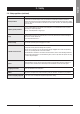
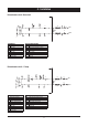
When two or several units are connected in parallel, to balance the
load losses of the various circuits, it is recommended to execute a
“reverse return” connection (see the diagram below).
UNIT 1
UNIT 2
Legend
S On/Off valves
VG Balancing valves
4.3 Water connections
The flow switch and the filter water, although not included in the
supply, must always be fitted such as plant components.
Their installation is mandatory for warranty.
WARNING
The attachments at the water inlet and outlet
shall be connected in compliance with the
instructions which can be found on the labels in
the proximity of the attachments.
Connect the water lines of the plants with the attachments of the unit
whose diameters and positions are shown in Chapter 9.
4.4 Defrost water drainage
(only for SyScroll Air HP units)
When heat pump units work in heating mode, during defrosting
cycles, they may discharge water from the base. This is why the
units should be installed at least 200 mm above the floor level, so
as to allow the free drainage of waste water, without the risk of
producing ice banks.
The heat pump units must be installed in positions where the
defrosting water cannot create any damage.
4.5 Water buffer tank
The accumulation tank which has been designed to be mounted
on SyScroll units is complete with all the hydraulic and electrical
components required for the correct operation of the system.
These systems are carefully assembled and tested at works. They
are ready for operation after having correctly realised all electrical
and hydraulic connections.
4.5.1 Supplied Material
The kits will be supplied with pipelines ready for installation. An
antifreeze resistance with wiring, an automatic water filling valve, a
3 bar safety valve, a drain valve and a vent valve have already been
assembled.
Hydrokit is shipped with a film to protect it from atmospheric agents.
Packaging has been designed in order to stack it up.
4.5.2 Antifreeze Electric Heater
The antifreeze resistance of the tank (TEH) shall be wired with the
panel as it is shown by the diagram attached to the unit.
4.5.3 Water Filter
The kit will use the water filter of the unit.