
UM SYSAQUA 20 210 (UM AQA 01 N 5GB)


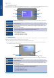


Table Of Contents
- SOMMAIRE
- 1. DESCRIPTION
- 2. PURPOSE
- 3. INTERFACES
- 4. THERMAL CONTROL
- 5. EQUIPMENT MANAGEMENT
- 6. ADDITIONAL FUNCTIONALITIES
- 7. CLIENT DIGITAL INPUTS AND PRIORITIES
- 8. PROTECTIONS, EVENTS AND ALARMS
- 9. USER INTERFACE
- 10. AUTOMATIC ARCHIVING
- 11. MANAGEMENT OF SITE AND APPLICATION PARAMETERS
- 12. COMMUNICATION
- 13. OVERVIEW OF THE HMI
- 14. LIST OF EVENTS
- 15. LIST OF ALARMS

English
-
+
-
+
K
p
K
p
/T
i
δ
SP*
Water temperature
Load
Actual setpoint
0%
100%
Step 8
Time
Step 7
Step 6
Step 5
Step 4
Step 3
Step 2
Step 1
Load
Capacity
17SYSAQUA
4.3. TEMPERATURE CONTROL
Temperature control ensures that the water sensor selected by the client (RWT or LWT) attains the actual
set-point, SP*. To manage the compressors more efciently, the control uses the concepts of load and
capacity.
Load formulation
The load is calculated via an algorithm PI
minimizing the difference between the unit
measurement and the set-point.
The coefcients of PI depend on the range,
the water temperature to be controlled and
the operating mode. They correspond to the
minimum volumes of water circuits indicated in
the IOM.
Capacity steps
The capacity of the unit is staged by combining the activations of the compressors. The capacity of a
step is proportional to the power of the activated compressors as is shown in the following table for a
SYSAQUA 210 :
Compressor Stepping
Circuit N° Power
0 1 2 3 4 5 6 7 8
1
C2 39.7
OFF ON OFF ON ON OFF ON OFF ON
C1 64.7
OFF OFF ON OFF OFF ON OFF ON ON
2
C2 39.7
OFF OFF OFF ON OFF OFF ON ON ON
C1 64.7
OFF OFF OFF OFF ON ON ON ON ON
Capacity (%)
0 19 31 38 50 62 69 81 100
Response to the client load
The temperature control dynamically adapts to the stepping of the capacity of the unit to the load of the
client water circuit.
Range
Temperature to
be controlled
Coefcient Units Cool mode Heat mode
SYSAQUA 20 to
125
RWT
K
p
%/K 10 10
T
i
s 60 60
LWT
K
p
%/K 4 4
T
i
s 50 50
SYSAQUA 140 to
210
RWT
K
p
%/K 10 10
T
i
s 60 60
LWT
K
p
%/K 4 5
T
i
s 180 60
Control of the water outlet temperature (LWT sensor), especially for SYSAQUA 20 to 125, requires precise
adjustment of the coefcients Kp and Ti. This adjustment depends on the installation, it can only be made
once the SYSAQUA is connected to the water circuit.
Information
The Kp and Ti coefcients can only be modied by a Systemair technician working on-site.