
DVG EC E8301 19 01 2017


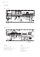

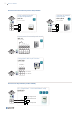

Wiring diagrams
Connection Functions
WD1 (1~230V)
WD2 (3~400V)
Power supply -
connection in
service switch
Power supply -
connection in
service switch
Control cables - connection in EC controller
Control cables - connection in EC controller
EC motor prewired
EC motor prewired
Max. crossection of power supply wires: 2,5 mm
2
(4 mm
2
without core end sleeves)
Cable glands on service switch for power supply: 1xM20x1,5
Service switch ON-OFF, 6-pole + 1x NC
Max. crossection of control wires: 1,5 mm
2
Cable glands of control part: 2x M20x1,5
F1 Fault relay
F2 Analog input for set value / speed setting
F3 Potentiometer for speed setting
F4 External sensor
F5 Speed output
F6 FIRE mode (open = FIRE)
F7 Start / Stop switch (open = stop)
F8 Modbus connection
8 Roof Fan DVG EC