
INSTALLATION OPERATION AND MAINTENANCE INSTRUCTION KV DUO KVK DUO KVK001

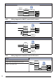


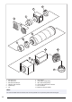


Table Of Contents
- 1Introduction
- 2Safety
- 3Transportation and storage
- 4Installation
- 4.1 To do before the installation of the product
- 4.2 To install the product
- 4.2.1 To open the product
- 4.2.2 To attach the connection box
- 4.2.3 To install the KVK Silent fan and the KVK Slim fan
- 4.2.4 To install the KVK DUO fan and the KVK fan
- 4.2.5 To install the KV DUO 150 EC fan
- 4.2.6 To install the KV DUO 250 – 315 EC fan
- 4.2.7 To install the KV DUO 400 – 630 EC fan
- 4.2.8 To connect the ducts to the product
- 5Electrical connection
- 6Commissioning
- 7Operation
- 8Maintenance
- 9Troubleshooting
- 10Disposal
- 11Warranty
- 12Technical data
- 13Accessory overview
- 14EU Declaration of Conformity
- 15UK Declaration of Conformity

MM6-24/D output signal selector
Compares signals from connected inputs and transfers the
signal to the control output.
1
2
3
4
5
6
Input 1 0...10 V
Input 2 0...10 V
Input 3 0...10 V
Input 4 0...10 V
Input 5 0...10 V
Input 6 0...10 V
7
8
9
10
11
12
System neutral
Mains
supply
24 V AC
Signal neutral
Signal neutral
Output minimum 0...10V
Output maximum 0...10V
PCA 1000D2 Pressure controller
For constant air volume control (CAV) or variable air volume
control (VAV).
GN
D
A GN
D
1(+) 2( )
+U
S
U
S
PCA 1000/6000D2
+
10...24 V DC
+ -
∆p
p
V
PI
R
i
= 4 kΩ
01
0 = Setpoint 1
1 = Setpoint 2
U
out
+
-
3
1
2
4
+
1. Mains supply 10....24 V DC
2. Output 0....10 V
3. Pressure connections
4. Voltage input for switch on Setpoint 1/Setpoint 2
13 Accessory overview
Note:
For more information about accessories, refer to www.systemair.com or speak to Systemair technical support.
31