
Manual
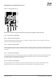


Table Of Contents
- VLT® HVAC Basic Drive FC 101
- English US
- Contents
- Introduction
- Safety
- Installation
- Mechanical Installation
- Electrical Installation
- Electrical Installation in General
- IT Mains
- Mains and Motor Connection
- Introduction
- Connecting to Mains and Motor
- Relays and Terminals on Enclosure Sizes H1–H5
- Relays and Terminals on Enclosure Size H6
- Relays and Terminals on Enclosure Size H7
- Relays and Terminals on Enclosure Size H8
- Connecting to Mains and Motor for Enclosure Size H9
- Relays and Terminals on Enclosure Size H10
- Enclosure Size I2
- Enclosure Size I3
- Enclosure Size I4
- IP54 Enclosure Sizes I2, I3, I4
- Enclosure size I6
- Enclosure size I7, I8
- Fuses and Circuit Breakers
- EMC-correct Electrical Installation
- Control Terminals
- Electrical Wiring
- Acoustic Noise or Vibration
- Programming
- Warnings and Alarms
- Specifications
- Index
- English US

3.2.7 Electrical Wiring
L1
L2
L3
3-phase
power
input
PE
PE
+10 V DC
0-10 V DC-
0-10 V DC-
50 (+10 V OUT)
54 (A IN)
53 (A IN)
55 (COM A IN/OUT)
0/4-20 mA
0/4-20 mA
42 0/4-20 mA A OUT / D OUT
45 0/4-20 mA A OUT / D OUT
18 (D IN)
19 (D IN)
27 (D IN/OUT)
29 (D IN/OUT)
12 (+24 V OUT)
24 V (NPN)
20 (COM D IN)
O V (PNP)
24 V (NPN)
O V (PNP)
24 V (NPN)
O V (PNP)
24 V (NPN)
O V (PNP)
Bus ter.
Bus ter.
RS485
Interface
RS485
(N RS485) 69
(P RS485) 68
(Com RS485 ) 61
(PNP)-Source
(NPN)-Sink
ON=Terminated
OFF=Unterminated
ON
1 2
240 V AC 3 A
Not present on all power sizes
Do not connect shield to 61
01
02
03
relay 1
relay 2
UDC+
UDC-
Motor
U
V
W
e30bd467.12
06
05
04
240 V AC 3 A
Illustration 25: Basic Wiring Schematic Drawing
NOTICE
There is no access to UDC- and UDC+ on the following units:
-
IP20, 380–480 V, 30–90 kW (40–125 hp)
-
IP20, 200–240 V, 15–45 kW (20–60 hp)
-
IP20, 525–600 V, 2.2–90 kW (3–125 hp)
-
IP54, 380–480 V, 22–90 kW (30–125 hp)
Installation
Operating Guide | VLT® HVAC Basic Drive FC 101
AQ275641848264en-000101 / 132R0078| 37
Danfoss A/S © 2019.11