
Manual


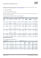

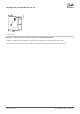
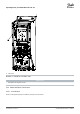


Table Of Contents
- VLT® HVAC Basic Drive FC 101
- English US
- Contents
- Introduction
- Safety
- Installation
- Mechanical Installation
- Electrical Installation
- Electrical Installation in General
- IT Mains
- Mains and Motor Connection
- Introduction
- Connecting to Mains and Motor
- Relays and Terminals on Enclosure Sizes H1–H5
- Relays and Terminals on Enclosure Size H6
- Relays and Terminals on Enclosure Size H7
- Relays and Terminals on Enclosure Size H8
- Connecting to Mains and Motor for Enclosure Size H9
- Relays and Terminals on Enclosure Size H10
- Enclosure Size I2
- Enclosure Size I3
- Enclosure Size I4
- IP54 Enclosure Sizes I2, I3, I4
- Enclosure size I6
- Enclosure size I7, I8
- Fuses and Circuit Breakers
- EMC-correct Electrical Installation
- Control Terminals
- Electrical Wiring
- Acoustic Noise or Vibration
- Programming
- Warnings and Alarms
- Specifications
- Index
- English US

3.2.3.4 Relays and Terminals on Enclosure Size H6
1
95
99
L1 91 / L2 92 / L3 93
U 96 /
V 97 /
W 98
03 02 01
06 05 04
2
3
4
e30bb762.11
1 Mains
3 Ground
2 Motor
4 Relays
Illustration 5: Enclosure Size H6 , IP20, 380–480 V, 30–45 kW (40–60 hp) , IP20, 200–240 V, 15–18.5 kW (20–25 hp) , IP20, 525–600 V, 22–30
kW (30–40 hp)
Installation
Operating Guide | VLT® HVAC Basic Drive FC 101
AQ275641848264en-000101 / 132R0078
20 | Danfoss A/S © 2019.11