
FC101 Design Guide


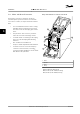

4.2.4 Decoupling Plate
Use the decoupling plate for EMC-correct installation.
Figure 4.8 shows the decoupling plate on an H3 enclosure.
130BB793.10
99 99
Figure 4.8 Decoupling Plate
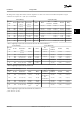
Power [kW(hp)] Decoupling plate
ordering numbers
Frame IP class 3x200–240 V 3x380–480 V 3x525–600 V
H1 IP20 0.25–1.5 (0.33–2.0) 0.37–1.5 (0.5–2.0) – 132B0202
H2 IP20 2.2 (3.0) 2.2–4 (3.0–5.4) – 132B0202
H3 IP20 3.7 (5.0) 5.5–7.5 (7.5–10) – 132B0204
H4 IP20 5.5–7.5 (7.5–10) 11–15 (15–20) – 132B0205
H5 IP20 11 (15) 18.5–22 (25–30) – 130B0205
H6 IP20 15–18.5 (20–25) 30 (40) 18.5–30 (25–40) 132B0207
H6 IP20 – 37–45 (50–60) – 132B0242
H7 IP20 22–30 (30–40) 55 (75) 37–55 (50–75) 132B0208
H7 IP20 – 75 (100) – 132B0243
H8 IP20 37-45 (50–60) 90 (125) 75–90 (100–125) 132B0209
Table 4.5 Decoupling Plate Specications
NOTICE!
For enclosure sizes H9 and H10, the decoupling plates are included in the accessory bag.
Selection and Ordering
VLT
®
HVAC Basic Drive FC 101
52 Danfoss A/S © 04/2018 All rights reserved. MG18C822
44