
L BAL E234 GB MANUAL


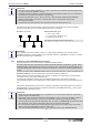


Table Of Contents
- 1 General notes
- 2 Safety instructions
- 2.1 Intended use
- 2.2 Explanations of symbols
- 2.3 Product safety
- 2.3 Product safety
- 2.4 Requirements placed on the personnel / due diligence
- 2.4 Requirements placed on the personnel / due diligence
- 2.5 Start–up and during operation
- 2.5 Start–up and during operation
- 2.6 Work on the device
- 2.6 Work on the device
- 2.7 Modifications / interventions in the device
- 2.7 Modifications / interventions in the device
- 2.8 Operator’s obligation of diligence
- 2.8 Operator’s obligation of diligence
- 2.9 Employment of external personnel
- 2.9 Employment of external personnel
- 3 Product overview
- 3 Product overview
- 4 Mounting
- 4 Mounting
- 4.1 General notes
- 4.1 General notes
- 4.2 Connection pressure measuring tube
- 4.2 Connection pressure measuring tube
- 4.3 Outdoor installation
- 4.3 Outdoor installation
- 4.4 Installation location for agriculture
- 4.4 Installation location for agriculture
- 4.5 Temperature influences during commissioning
- 4.5 Temperature influences during commissioning
- 5 Electrical installation
- 5 Electrical installation
- 5.1 Safety precautions
- 5.1 Safety precautions
- 5.2 EMC–compatible installation of control lines
- 5.2 EMC–compatible installation of control lines
- 5.3 Mains connection
- 5.3 Mains connection
- 5.4 Signal input or sensor connection (E2)
- 5.4 Signal input or sensor connection (E2)
- 5.5 Control outputs 0 – 10V (A1, A2)
- 5.5 Control outputs 0 – 10V (A1, A2)
- 5.6 Voltage supply for external devices (+, GND)
- 5.6 Voltage supply for external devices (+, GND)
- 5.7 Digital inputs (D1, D2)
- 5.7 Digital inputs (D1, D2)
- 5.8 Relay outputs
- 5.8 Relay outputs
- 5.9 RS–485 interfaces for MODBUS RTU
- 5.9 RS–485 interfaces for MODBUS RTU
- 5.10 USB–interface
- 5.10 USB–interface
- 5.11 Potential at control voltage connections
- 5.11 Potential at control voltage connections
- 6 Select operation mode
- 6 Select operation mode
- 7 Start–up
- 8 Controls and Menu
- 9 Programming
- 9.1 Pressure control airconditioning
- 9.2 Menu group Start
- 9.3 Menu group Info
- 9.4 Controller Setup
- 9.4.1 PIN protection
- 9.4.2 PIN protection
- 9.4.3 user settings
- 9.4.4 Sensor Alarm ON / OFF
- 9.4.5 Limit
- 9.4.6 Minimum speed cut off
- 9.4.7 Reverse action of the control function
- 9.4.8 Controller configuration
- 9.4.9 Group control
- 9.4.10 Display text for external message
- 9.4.11 Offset control signal
- 9.4.12 Selection amplifier (comparator) control circuit 1 or 2 at output A1
- 9.4.13 Data on the total control deviation
- 9.5 IO Setup
- 9.5.1 Analog outputs
- 9.5.2 Digital inputs
- 9.5.2.1 Menu overview
- 9.5.2.2 Enable
- 9.5.2.3 External message, Function
- 9.5.2.4 Limit ON / OFF, Function
- 9.5.2.5 Switch over input
- 9.5.2.6 Output control circuit 2 additional to
- 9.5.2.7 Set 1/2 or Setpoint 1/2, Function
- 9.5.2.8 Intern / Extern Function
- 9.5.2.9 Automatic control / speed manual Function
- 9.5.2.10 Reverse action of control function (
- 9.5.2.11 Switch over Setpoint 1/2 for control circuit 2
- 9.5.2.12 Setting Max. Speed ON / OFF function
- 9.5.2.13 Switch over Setpoint 1/2 and Pband 1/ 2 for control circuit 1
- 9.5.2.14 Switch over Setpoint 1/2 and Pband 1/2 for control circuit 2
- 9.5.2.15 Timer function overwrite
- 9.5.3 Configuration of analog inputs
- 9.5.4 Function and inverting for relay outputs
- 9.5.5 COM2
- 9.6 Limits
- 9.7 Timer
- 9.8 MODBUS Slave
- 9.9 MODBUS Master
- 9.10 Member MOBUS Master
- 10 Menu tables
- 10
- 11 Diagnostics menu
- 12 Protocol
- 13 Enclosure

5.8 Relay outputs (K1, K2)
Various functions can be allocated to the relay outputs “K1” and “K2” (
IO Setup: function and
inverting relais outputs). Max. contact rating
technical data and connection diagram.
Relays K1
•
Connection of the floating contacts of relay “K1” to the terminals 11, 14, 12.
•
“K1 Function” factory setting:
|
1K
|
= Operating indication. I.e. energized for operation without
fault, for enable “OFF” de-energized.
Relays K2
•
Connection of the floating contacts of relay “K2” to the terminals 21, 24, 22.
•
“K2 Function” factory setting:
|
2K
|
= Fault indication. I.e. energized for operation without fault and
for enable “OFF”.
5.9 RS-485 interfaces for MODBUS RTU
The device has two RS-485 interfaces for networking via MODBUS RTU:
1. Interface “1A (1D+)”, “1B (1D-)” for MODBUS Master applications
– Pre-programmed function is output from control circuit 1:
|
1. Control signal (2A)
|
e.g. for activating speed controllers for fans or fans with integrated controller and MODBUS
interface (
member MODBUS Master).
The programmable functions correspond to the functions for the analogue outputs described in
the IO Setup.
– Automatic addressing of members via a patented procedure.
It is no longer necessary to address each individual member manually in the network. The “ID”
connection is also assigned (for more information
the following chapter). .
– Integrated failsafe wiring and 150 Ω termination.
2. Interface “2A (2D+)”, “2B (2D-)” for MODBUS Slave applications
– Connection of the device to a superordinate building control system.
– Setting of address and communication parameters
Programming: Menu group MODBUS
Slave.
GND
2A (2D+)
2B (2D-)
GND
A (D+)
B (D-)
CXE / CXG
MODBUS Slave
MODBUS Slave
GND
1A (D+)
1B (1D-)
GND
A (D+)
B (D-)
CXE / CXG
MODBUS Master
MODBUS Slave
ID
ID2
ID1
13.03.2013
v_cxe_modbus_master_u_slave_anschl.vsd
Connection MODBUS Slave and MODBUS Master interface
When using telephone flex with four cable cores, we recommend the following allocation:
•
A (D+) = red
•
B (D-) = black
•
ID - ID1/2 = yellow (for automatic addressing for MODBUS Master)
•
GND = white
Operating Instructions POC-M Electrical installation
L-BAL-E234-GB 1614 Index 002 Part.-No.
12/84