
L BAL E234 GB MANUAL


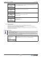


Table Of Contents
- 1 General notes
- 2 Safety instructions
- 2.1 Intended use
- 2.2 Explanations of symbols
- 2.3 Product safety
- 2.3 Product safety
- 2.4 Requirements placed on the personnel / due diligence
- 2.4 Requirements placed on the personnel / due diligence
- 2.5 Start–up and during operation
- 2.5 Start–up and during operation
- 2.6 Work on the device
- 2.6 Work on the device
- 2.7 Modifications / interventions in the device
- 2.7 Modifications / interventions in the device
- 2.8 Operator’s obligation of diligence
- 2.8 Operator’s obligation of diligence
- 2.9 Employment of external personnel
- 2.9 Employment of external personnel
- 3 Product overview
- 3 Product overview
- 4 Mounting
- 4 Mounting
- 4.1 General notes
- 4.1 General notes
- 4.2 Connection pressure measuring tube
- 4.2 Connection pressure measuring tube
- 4.3 Outdoor installation
- 4.3 Outdoor installation
- 4.4 Installation location for agriculture
- 4.4 Installation location for agriculture
- 4.5 Temperature influences during commissioning
- 4.5 Temperature influences during commissioning
- 5 Electrical installation
- 5 Electrical installation
- 5.1 Safety precautions
- 5.1 Safety precautions
- 5.2 EMC–compatible installation of control lines
- 5.2 EMC–compatible installation of control lines
- 5.3 Mains connection
- 5.3 Mains connection
- 5.4 Signal input or sensor connection (E2)
- 5.4 Signal input or sensor connection (E2)
- 5.5 Control outputs 0 – 10V (A1, A2)
- 5.5 Control outputs 0 – 10V (A1, A2)
- 5.6 Voltage supply for external devices (+, GND)
- 5.6 Voltage supply for external devices (+, GND)
- 5.7 Digital inputs (D1, D2)
- 5.7 Digital inputs (D1, D2)
- 5.8 Relay outputs
- 5.8 Relay outputs
- 5.9 RS–485 interfaces for MODBUS RTU
- 5.9 RS–485 interfaces for MODBUS RTU
- 5.10 USB–interface
- 5.10 USB–interface
- 5.11 Potential at control voltage connections
- 5.11 Potential at control voltage connections
- 6 Select operation mode
- 6 Select operation mode
- 7 Start–up
- 8 Controls and Menu
- 9 Programming
- 9.1 Pressure control airconditioning
- 9.2 Menu group Start
- 9.3 Menu group Info
- 9.4 Controller Setup
- 9.4.1 PIN protection
- 9.4.2 PIN protection
- 9.4.3 user settings
- 9.4.4 Sensor Alarm ON / OFF
- 9.4.5 Limit
- 9.4.6 Minimum speed cut off
- 9.4.7 Reverse action of the control function
- 9.4.8 Controller configuration
- 9.4.9 Group control
- 9.4.10 Display text for external message
- 9.4.11 Offset control signal
- 9.4.12 Selection amplifier (comparator) control circuit 1 or 2 at output A1
- 9.4.13 Data on the total control deviation
- 9.5 IO Setup
- 9.5.1 Analog outputs
- 9.5.2 Digital inputs
- 9.5.2.1 Menu overview
- 9.5.2.2 Enable
- 9.5.2.3 External message, Function
- 9.5.2.4 Limit ON / OFF, Function
- 9.5.2.5 Switch over input
- 9.5.2.6 Output control circuit 2 additional to
- 9.5.2.7 Set 1/2 or Setpoint 1/2, Function
- 9.5.2.8 Intern / Extern Function
- 9.5.2.9 Automatic control / speed manual Function
- 9.5.2.10 Reverse action of control function (
- 9.5.2.11 Switch over Setpoint 1/2 for control circuit 2
- 9.5.2.12 Setting Max. Speed ON / OFF function
- 9.5.2.13 Switch over Setpoint 1/2 and Pband 1/ 2 for control circuit 1
- 9.5.2.14 Switch over Setpoint 1/2 and Pband 1/2 for control circuit 2
- 9.5.2.15 Timer function overwrite
- 9.5.3 Configuration of analog inputs
- 9.5.4 Function and inverting for relay outputs
- 9.5.5 COM2
- 9.6 Limits
- 9.7 Timer
- 9.8 MODBUS Slave
- 9.9 MODBUS Master
- 9.10 Member MOBUS Master
- 10 Menu tables
- 10
- 11 Diagnostics menu
- 12 Protocol
- 13 Enclosure

10.2 Possible allocation of the IOs, PINs
Units for analog inputs E1 and E2
The following units can be set for programmed sensors with free measuring range (0 - 10 V, 0 - 20 mA, 4 -
20 mA).
E1 Analog In
E2 Analog In
°C, m
3
/h, bar, %, Pa, m/s, m
3
/s, Ohm, mbr, °F, ft/s, cfm, in.wg, psi, ppm
Analog outputs A1 and A2
Function Description
OFF no function
Constant voltage 10 V
(1A)
Constant voltage +10 V
Factory setting for “A2” at operation with one control circuit.
1st control signal
(2A)
Controlled 0 - 10 V output for control circuit 1 (factory setting for “A1”)
E1
(3A)
proportional input “E1”
E2
(4A)
proportional input “E2”
Group2
(5A)
Group control (
Controller Setup - group 2)
2.Cooling
(6A)
Only for mode
2.03 temperature controller with additional functions.
Controller output 2 with rising activation at Actual>Nominal = Cool.
2.Heating
(7A)
Only for mode
2.03 temperature controller with additional functions.
Controller output 2 with rising activation at Actual<Nominal = Heat.
2. control signal
(8A)
Controlled 0 - 10 V output vor control circuit 2.
Factory setting for “A2” at operation with second control circuit.
A second control circuit can be activated if required by programming the E2 function
(
Base Setup E2 functions 8E - 13E and second control circuit)
Speed
(9A)
proportionally 1.Control signal
Group1
(10A)
Group control (
Controller Setup - group 1)
Group3
(11A)
Group control (
Controller Setup - group 3)
Group4
(12A)
Group control (
Controller Setup - group 4)
Digital inputs D1 and D2
Function Description
OFF
No function (factory setting for D2)
Enable
(1D)
Enable (remote control) “ON” / “OFF”
External error
(2D)
External fault alarm
Limit
(3D)
“Limit” ON / OFF
Influences control circuit 1 and control circuit 2
E1 / E2
(4D)
Switch over input “E1” / “E2” (for operation with one control circuit)
Setpoint1/2
(5D)
Switch over “Setpoint 1” / “Setpoint 2” für control circuit 1 (factory Setting for D1)
Operating Instructions POC-M Menu tables
L-BAL-E234-GB 1614 Index 002 Part.-No.
70/84