
L BAL E231 GB QUICK START


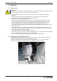


Table Of Contents

4 Mounting
4.1 General notes
Attention!
The following points must be complied with during the mechanical installation to avoid causing a defect
in the device due to assembly errors or environmental influences:
•
Before installation remove the device from the packing and check for any possible shipping
damage!
•
Assemble the device on a clean and stable base. Do not distort during assembly! Use the
appropriate mounting devices for proper installation of the unit!
•
Do not mount equipment on vibrating base!
•
When mounted onto lightweight walls, there must be no impermissibly high vibrations or shock
loads. Any banging shut of doors that are integrated into these lightweight walls, can result in
extremely high shock loads. Therefore, we advise you to decouple the devices from the wall.
•
Do not allow drilling chips, screws and other foreign bodies to reach the device interior!
•
The device should be installed in a location where it will not be disturbed, but at the same time can
be easily accessed!
•
Depending on the housing model use supplied stoppers for cable inlets, cut off necessary cable
inlets respectively to the cable diameter. Or alternative use cable inlet for cable glands. Any cable
ducts openings not used must be sealed!
•
Care must be taken to avoid direct radiation from the sun!
•
The device is designed for vertical installation (cable inlet down). A horizontal or reclined installation
is only permissible after technical release of the manufacturer!
•
Be sure to observe proper heat dissipation (
Technical data, heat dissipation).
4.2 Connection pressure measuring tube
Depending on the tube diamater cut the cable entries and bring in measuring tubes into the device.
Connection of the tubes directly to the internal pressure sensor.
The excess pressure tube must be connected to the white side here “P1” (+) and the negative
pressure tube connected to the black side “P2” (-) (connection piece Ø : 6.2 mm).
Quick Start Guide POC-M Mounting
L-BAL-E231-GB 1446 Index 001 Part.-No. 00163429-42
5/15