
IOM WQ 20 190 354455


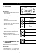


Table Of Contents

27
English
6 - Control (continued)
ICON / COLOR
LED N°*
STEADY ICON
DESCRIPTION
BLINKING ICON
ICON
- Alarm ON
First capacity step
Second capacity step
Primary circuit pump
Source circuit pump
Electrical heater
Sanitary hot water valve / pump
Boiler
/ RED
1
2
3
4
5
6
7
/ GREEN
/ GREEN
/ GREEN
/ GREEN
/ GREEN
/ RED
/ RED
/ RED
/ RED
/ RED
- Mode: HEATING
- Current HR
- Time slots activ.
- Mode: COOLING
/
/
/
- Mode: STAND-BY
- Configurable
Not used
Menu surf
- Alarm QUIT
- Antifreeze+Heat pump ON
- Heating mode by remote
- HR setting
- Time slots programming
- Cooling mode by remote
/
/
/
- Stand-by mode by remote
- Configurable
Not used
/
6.3 Folder structure
Folder structure is composed of totally four menus
1) Main display → used to set what to display without acting on any
key
– Ai → analogue input (temperature, pressure)
– rtC → room time clock
– SetP → standard set-point
– SetR → corrected set-point (according to climatic correction,
etc.)
2) Operating mode → used to set operating mode
– StbY → stand-by
– HEAT → heating
– COOL → cooling
– AS → sanitary hot water
3) Status → used to show resources values
– Ai (AIL/AIE/Air) → analogue inputs (main board / expansion
board / remote terminal)
– di (diL/diE) → digital inputs (main board / expansion board)
– AO (AOL/AOE) → analogue outputs (main board/expansion
board)
– CL (HOUr/dAtE/YEAr) → clock
– AL (Er00 → Er98) → alarms
– SP → standard set-point
– Sr → corrected set-point (according to climatic correction,
etc.)
4) Program → define parameters, functions, password and to display
alarm log
6.4 Menu structure
“Program” menu is composed of totally four folders
1) Parameters → change unit parameters
2) Functions → manual operations (switch ON / switch OFF, alarm
quit, historic alarm delete, multi function key use)
3) Password → define visibility levels for parameters/folders
4) Alarm log → display alarm log
Parameter folder gives access to following sub-folders
– CL/CE/Cr/CF → configure device I/O (L → local; E → expansion;
r → remote; F → serial)
• analogue inputs (type of probe, range, differential, logic
function)
• digital inputs (logic function)
• digital outputs (logic function)
• analogue outputs (range)
• serial configuration (communication parameters)
– TR → define thermoregulation parameters
• set-point (max/min/hysteresis)
• type (proportional/differential)
• probe selection
– ST → define operating status
• cooling only
• heating only
• scooling and heating
• change-over
– CP → configure compressor parameters (type/number/timing)
– PI/PE → define primary circuit / source side circuit pump
parameters / functions
• operating mode (disable / always ON / ON if compressor ON)
• digital / analogue control
• anti-sticking
• anti-freeze
– BR → control the parameters for an additional step for heating
and for sanitary hot water integration (boiler)
• operating mode (disable / differential → fixed or in function of
outdoor air temperature)
• set-point / hysteresis
– DS → define set-point offset (dynamic set-point) depending on
• analogue input (0…1V, 0…5V, 0…10V, 4…20mA)
• outdoor air temperature
• room temperature
– AD → simulate an electronic inertial accumulator, acting on set-
point and hysteresis (adaptive function), by confronting minimum
/ effective ON-OFF time
– AS → define sanitary hot water management parameters
• operating mode (disable / sanitary hot water valve / resistance
/ pump)
• set-point / hysteresis
• anti-legionella function
– HP → define heat pump block management parameters
• outdoor air temperature
• thermoregulation temperature
• digital input
– PL → define capacity limitation to protect the unit (high/low T,
high/low P)
– TE → define time slots management (different operating daily
profiles)
– AL → define alarms management (automatic / manual reset, by-
pass time, sampling)