
SYSLOGIC – Installation Operation Manual (IOM LOGIC 02 N 3GB)


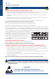


Table Of Contents

English
0.5...0.6
N•m
C
Ø 3.5 mm
22...1322...1324…1324…13
AWG
0.25…2.50.25…2.50.2…2.50.2…2.5
2
mm
mm
7
DANGER
The main board is sensitive to electrostatic discharges. Eliminate electrostatic discharges
appropriately (by means of anti-static bracelets, shoe-covers, etc.) before handling and installing
the electronic device.
Caution
4 SYSLOGIC
2. ELECTRICAL CONNECTIONS
UNINTENDED EQUIPMENT OPERATION DUE TO ELECTROSTATIC DISCHARGE DAMAGE
² Keep equipment in the protective conductive packaging until you are ready to install the equipment.
² Only install equipment in approved enclosures and / or locations that prevent unauthorized access
and provide electrostatic discharge protection as dened by IEC 1000-4-2.
² Use a conductive wrist strap or equivalent eld force protective device attached to an earth ground
when handling sensitive equipment.
² Always discharge yourself by touching a grounded surface or approved antistatic mat before
handling the equipment.
Failure to follow these instructions can result in death, serious injury, or equipment damage.
HAZARD OF ELECTRIC SHOCK, EXPLOSION OR ARC FLASH
² Disconnect all power from all equipment including connected devices, prior to removing any covers
or doors, or installing or removing any accessories, hardware, cables, or wires.
² Always use a properly rated voltage sensing device to conrm the power is off where and when
indicated.
² Replace and secure all covers, accessories, hardware, cables, and wires and conrm that a proper
ground connection exists before applying power to the unit.
² Use only the specied voltage when operating this device and any associated products.
Failure to follow these instructions can result in death, serious injury.
This device has been designed to operate outside of any hazardous location.
Only install this device in zones known to be free of hazardous atmosphere.
The device is equipped with screw-type or removable terminal boards for connection of wires having a
maximum cross section of 2.5 mm2 - 13 AWG (a single conductor per terminal for the power connections):
refer to the label on the instrument for details of the terminal ratings. Do not exceed the maximum permitted
current; for higher loads, use a contactor with sufcient power capacity. Probes have no connection polarity
and can be extended using a normal two-core cable (note
that extension of the probe leads inuences the instrument’s
electromagnetic compatibility - EMC: take great care with the
wiring). Probe cables, power supply cables and the TTL serial
cables should be routed separately from power cables.
The following table presents the cable types and wire sizes for
a 5.00 or 5.08 pitch removable screw terminals block:
LOOSE WIRING CAUSES ELECTRIC SHOCK
Tighten connections in conformance with the torque specications.
Failure to follow these instructions will result in death or serious injury.
CAUTION
OBSERVE PRECAUTIONS FOR HANDLING
ELECTROSTATIC DISCHARGE SENSITIVE DEVICES